C O NFIG URA TIO N
1 7 3
UNIV ERS AL INPU TS 3
UIP2 (T 2) SET UP 4
UIP2 (T 2) SET UP 4
3 2 9)UIP2 T HRESH OLD
UIP2 (T 2) SET UP 4
3 2 0)UIP2 IP RA N GE
UIP2 (T 2) SET UP 4
3 2 2)UIP2 C AL RA TIO
UIP2 (T 2) SET UP 4
3 2 3)UIP2 M A X CL A MP
UIP2 (T 2) SET UP 4
3 2 4)UIP2 MIN CL A MP
UIP2 (T 2) SET UP 4
UIP A N ALO G G O T O
UIP2 (T 2) SET UP 4
UIP DIGIT AL OP1 G O T O
UIP2 (T 2) SET UP 4
3 2 1)UIP2 IP O FFSE T
UIP2 (T 2) SET UP 4
UIP DIGIT AL OP2 G O T O
UIP2 (T 2) SET UP 4
3 2 5)UIP2 HI V AL OP1
UIP2 (T 2) SET UP 4
3 2 6)UIP2 LO V AL OP1
UIP2 (T 2) SET UP 4
3 2 7)UIP2 HI V AL OP2
UIP2 (T 2) SET UP 4
3 2 8)UIP2 LO V AL OP2
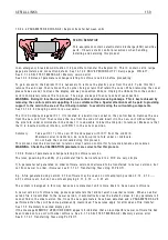
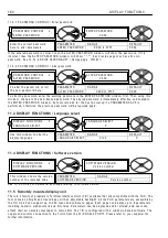
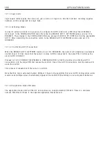
UNIV ERS AL INPU TS / UIP2 to 9
Th
i
s sho w s the UIP2 submenu
There are 8 sub menus, one for each
i
nput 2 to 9
Each
i
nput term
i
na
l
UIP2 to 9
i
s prov
i
ded w
i
th
i
ts
o w n process
i
ng b
l
ock w
i
th a
li
near and
l
og
i
c
output. It a
ll
o w s the fo
ll
o w
i
ng funct
i
ons.
Range se
l
ectab
l
e + /- (5, 1 0, 2 0, 3 0 V).
L
i
near funct
i
ons.
L
i
near offset.
S
i
gned sca
li
ng.
C
l
amp
i
ng of the
li
near output.
Log
i
c funct
i
ons.
A d
j
ustab
l
e thresho
l
d for
l
og
i
c
l
eve
l
detect
i
on.
The comparator output
i
s a
l
o w or a h
i
gh. The
h
i
gh state resu
l
ts
i
n the HI V ALUE be
i
ng output.
The
l
o w state resu
l
ts
i
n the LO V ALUE output.
Not
e
. U
I
P
s off
e
r
good no
i
s
e
i
mmun
i
ty.
The LO and HI va
l
ues can be entered us
i
ng the
d
i
sp
l
ay and keys, or may be connected from other
PINs us
i
ng JU MPERS. Th
i
s turns the funct
i
on
i
nto
a change-over s w
i
tch for dynam
i
c va
l
ues.
There are 2 sets of va
l
ue for h
i
gh and va
l
ue for
l
o w w
i
ndo w s each pa
i
r hav
i
ng
i
ts o w n G O T O
connect
i
on fac
ili
ty. Th
i
s a
ll
o w s 2
i
ndependent
output va
l
ues for a
l
og
i
c h
i
gh
i
nput and 2
i
ndependent output va
l
ues for a
l
og
i
c
l
o w
i
nput.
Th
i
s fac
ili
ty a
ll
o w s versat
il
e parameter changeover
funct
i
ons to be se
l
ected by a s
i
ng
l
e
i
nput.
E.g. DIG OP1 G O T O va
l
ue change to target PIN x,
DIG OP2 G O T O s
i
mu
l
taneous
l
og
i
c change to
target PIN y.
For
l
og
i
c on
l
y usage a va
l
ue of 0.0 0 %
i
s read as a
l
o w . A ny non zero + /- va
l
ue
i
s read as a h
i
gh.
Log
i
c
i
nvers
i
on
i
s accomp
li
shed by enter
i
ng
0.0 0 %
i
n the va
l
ue for HI w
i
ndo w and 0.0 1 %
i
n
the va
l
ue for LO w
i
ndo w .
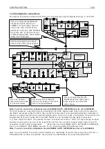
Range
PIN 3 2 0
T 2
UIP2
Input
A N ALO G
G O T O
PIN 3 2 2
Sca
l
er
PIN 3 2 1
O ffset
PIN 3 2 5 / PIN 3 2 7
H
i
gh
Lo w
PIN 3 2 6 / PIN 3 2 8
G O T O OP1
H
i
gh va
l
ue 1
Lo w va
l
ue 1
H
i
gh va
l
ue 2
Lo w va
l
ue 2
G O T O OP2
PIN 1 6 2
D
i
g mon
Thresho
l
d
PIN
3 2 9
PIN 3 2 3
PIN 3 2 4
A na
l
og
mon
i
tor
PIN 1 5 0
Summary of Contents for PLX
Page 2: ...2 Contents ...
Page 202: ......


