3. Physical installation of a MiPIX display system
•
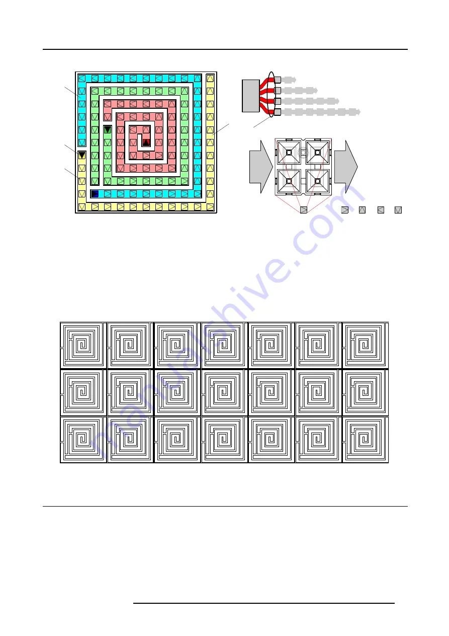
Tile with 11 x 11 MiPIX blocks.
A
1
2
3
4
1
2
3
4
IN
OUT
0
1
2
3
0º
90º
180º
270º
B
C
D
MiPIX
controller
D
1
2
3
4
Image 3-3
Legend:
A
Chain of MiPIX blocks.
B
Input (connection with controller) of the chain.
C
Represent a pixel block with a certain orientation (0º, 90º, 180º or 270º).
D
Output port number of the MiPIX control unit to which this chain is connected.
The tile configuration consist of four chains of MiPIX blocks placed in a spiral. Starting from the middle of the tile, coming out counter
clockwise. The first three chains contains 128 pixels or 32 MiPIX-20 blocks. The last chain contains 100 pixels or 25 MiPIX-20
blocks. The input (connection with the controller) of the chain is fixed as illustrated above. Note that the physical orientation of the
MiPIX-20 blocks for tile configuration must correspond with the above scheme.
The tile configuration is most suitable when you want to create your own MiPIX tiles. Using this tile configuration on a frame with a
square shape support grid and with on the back of the frame the MiPIX control unit mounted, gives you a customized LED tile. This
tile can easily be used to create very large MiPIX displays. See example below.
11 x 11
11 x 11
11 x 11
11 x 11
11 x 11
11 x 11
11 x 11
11 x 11
11 x 11
11 x 11
11 x 11
11 x 11
11 x 11
11 x 11
11 x 11
11 x 11
11 x 11
11 x 11
11 x 11
11 x 11
11 x 11
Image 3-4
3.3 Attach MiPIX-20 blocks to the support grid
What has to be done ?
The MiPIX-20 blocks has to be inserted in the support grid and connected with each other according a supported configuration
scheme. For more information on physical positions of pixel blocks, in relation to each other, and electrical connections, see Con-
figuration schemes of MiPIX blocks, page 15.
There are two methods of installing MiPIX-20 blocks. The first method is to snap the MiPIX-20 blocks into the support grid first and
then plug in the inter-block cable between the MiPIX-20 blocks. The second method is the other way around. First connect the
inter-block cable with the MiPIX-20 blocks and then snap in the MiPIX-20 blocks. The second method can be very handy in case
there is insufficient space behind the support grid.
R5976717 MIPIX-20 07042004
17


