601
–
0445 /05
Loki
97
Picture Left
Picture Right
Blend Zone
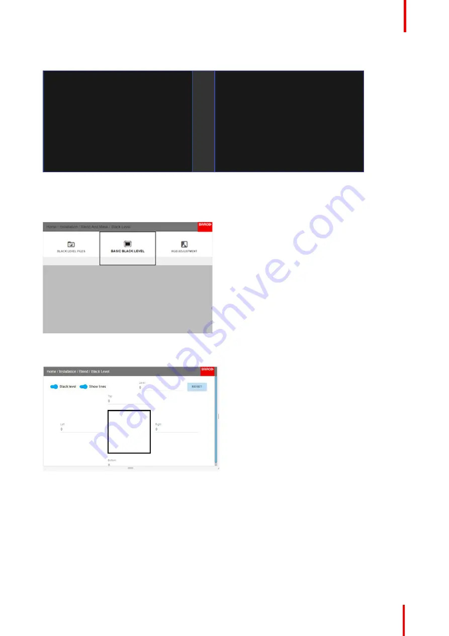
Image 8-48
How to adjust the level manually
1.
In the main menu, select the Basic Black level menu
Image 8-49
2.
Enable the
”
Black level
”
and
“
Show lines
”
buttons.
Image 8-50
3.
Move the cursor to the side where the overlapped area occurs. (Left/right/top/bottom.) For the left projector,
this will be the right side in the menu. Press enter, and adjust the value with the arrow keys. As mentioned
earlier, the value shall be slightly larger than the blend zone offset. A line that indicates the zone will also be
visible when
“
Show lines
”
is enabled. When the black level zone is optimal, press enter.
The value can also be entered by the numeric keys in the remote control.
4.
Move the cursor to
“
Level
”
, press enter and adjust this level until the black level equals the level in the blend
zone.
This value can also be entered by the numeric keys on the remote control.
Summary of Contents for Loki
Page 1: ...ENABLING BRIGHT OUTCOMES Installation Manual Loki...
Page 8: ...601 0445 05 Loki 8...
Page 20: ...601 0445 05 Loki 20 Safety...
Page 26: ...601 0445 05 Loki 26 Image 2 6 Image 2 7 All calibrations performed and OK Lenses...
Page 38: ...601 0445 05 Loki 38 Physical installation...
Page 48: ...601 0445 05 Loki 48 Getting started...
Page 70: ...601 0445 05 Loki 70 Image menu...
Page 71: ...71 601 0445 05 Loki Advanced picture adjustments 7...
Page 76: ...601 0445 05 Loki 76 Advanced picture adjustments...
Page 106: ...601 0445 05 Loki 106 Installation menu...
Page 116: ...601 0445 05 Loki 116 Status menu...
Page 120: ...601 0445 05 Loki 120 3D...
Page 121: ...121 601 0445 05 Loki Risk Group 3 Safety 12...


