


14. Communicator touch panel
14.1 Introduction
Communicator Touch Panel for digital cinema projectors
The Communicator Touch Panel is designed for multi-user command and control, the Communicator enables users to learn quickly
and operate ef
fi
ciently - using an elegant and
fl
exible touch panel interface. The interface’s commonality means that operators
can intuitively use any model in the product line, without restriction, and its user-friendly nature translates directly into a short and
enjoyable learning curve.
Image 14-1
Flexible touch panel interface
The touch panel interface can be mounted upon a swivel arm which easily
fi
ts on top of the DP2K-12C/11CX projector. One central
locking mechanism of the swivel arm allows an instant
fi
xation of the touch panel interface in any position.
The touch panel interface can also be installed further away from the DP2K-12C/11CX projector. For that you can use a serial
(RS232) cable up to 10 meter or an Ethernet cable up to 50 meter to realize a direct data communication between the DP2K-
12C/11CX projector and the Communicator Touch Panel.
The touch panel interface can also be connected with a Local Area Network (LAN) just like the DP2K-12C/11CX projector. In this
case both devices can communicate with each other as well.
The touch panel interface requires a voltage 12 VDC and 1,5 ampere. Note that the DP2K-12C/11CX projector has a 12
VDC output which can be used to power up the touch panel interface. Nevertheless, the use of a se12 VDC adaptor (1,5
ampere minimum) is required in case the touch panel interface is installed more then a few meters away from the DP2K-12C/11CX
projector.
A crossed DC cable has to be used when connecting the +12 VDC output from the Input & Communication
unit of the DP2K-12C/11CX projector directly with the Touch Panel interface.
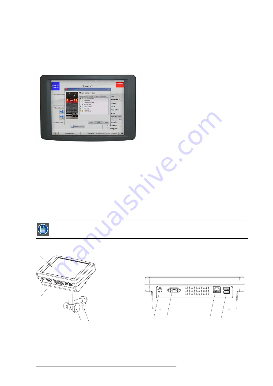
Parts location of the touch panel interface
E
B
C
D
A
F
G
H
Image 14-2
A
Touch screen.
B
Communication ports.
C
Knob to operate central swivel clamp.
D
Base of swivel arm.
E
Power input (12 VDC – 1,5 A).
F
RS323 port (9 pins SUB-D ).
G
Ethernet port (RJ45).
H
Two USB ports to connect USB stick, mouse or keyboard.
262
R5905043 DP2K-12C/11CX 19/02/2018
Summary of Contents for DP2K-12C
Page 1: ...DP2K 12C 11CX Service manual R5905043 15 19 02 2018...
Page 4: ......
Page 8: ...Table of contents 4 R5905043 DP2K 12C 11CX 19 02 2018...
Page 12: ...1 Safety 8 R5905043 DP2K 12C 11CX 19 02 2018...
Page 31: ...4 Troubleshooting 4 TROUBLESHOOTING R5905043 DP2K 12C 11CX 19 02 2018 27...
Page 32: ...4 Troubleshooting 28 R5905043 DP2K 12C 11CX 19 02 2018...
Page 96: ...5 Removal and installation of projector covers 92 R5905043 DP2K 12C 11CX 19 02 2018...
Page 121: ...6 Lamps and lamp houses Image 6 38 R5905043 DP2K 12C 11CX 19 02 2018 117...
Page 138: ...7 Cold mirror assembly 134 R5905043 DP2K 12C 11CX 19 02 2018...
Page 222: ...12 Card Cage 1 Image 12 11 218 R5905043 DP2K 12C 11CX 19 02 2018...
Page 225: ...12 Card Cage Image 12 15 Button unit removal R5905043 DP2K 12C 11CX 19 02 2018 221...
Page 281: ...15 Power input Image 15 13 Mains AC compartment cover R5905043 DP2K 12C 11CX 19 02 2018 277...
Page 282: ...15 Power input 278 R5905043 DP2K 12C 11CX 19 02 2018...
Page 306: ...18 Lamp power supply single module 302 R5905043 DP2K 12C 11CX 19 02 2018...
Page 340: ...21 Maintenance procedures 336 R5905043 DP2K 12C 11CX 19 02 2018...
Page 350: ...A Pin configurations 346 R5905043 DP2K 12C 11CX 19 02 2018...
Page 351: ...B Input formats B INPUT FORMATS R5905043 DP2K 12C 11CX 19 02 2018 347...
Page 352: ...B Input formats 348 R5905043 DP2K 12C 11CX 19 02 2018...


