


9
Troubleshooting
Problem
Possible Causes / Solutions
Directional Counts are not changing
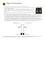
Sensors may not be properly aligned. Realign the sensors.
Batteries may need to be replaced
Directional Count is opposite of expectation
Sensors pair may be installed in reverse order. Verify sensors A and B are installed in the correct order.
Sensors are double counting
Sensors may not be properly aligned. Realign the sensors.
Adjust the sensor height to avoid carts and other objects triggering the sensors.
Sensors missing directional counts or over
counting
People may be entering side-by-side, causing the sensors to view a single count instead of two people.
People stopping in the middle of the beam path may block others coming through and being counted.
If someone walks into the beam path without going through completely, stops, then turns around, the
person may not have been counted properly.
Recommend instructing people to walk through in a single file pattern and not to stop in front of the
sensor’s beam path.
Counts reset unexpectedly
Pushing the back arrow on the Operator Interface clears all the counts, similar to the daily reset.
All counts reset overnight
The DXM Controller is programmed to reset all counts at 2 AM Central (observing DST).
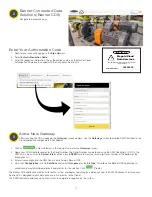
Contact your local distributor or Banner Engineering’s technical support team at 1-800-203-5616 for
assistance on changing the reset schedule.
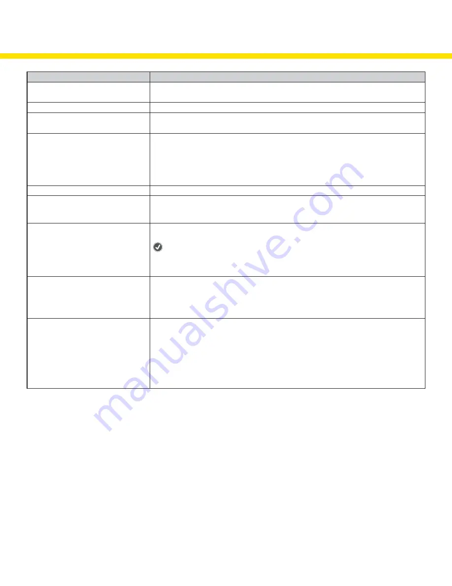
Operator Interface no longer displays the
counts
After the DXM Controller is rebooted, a delay of 5 minutes may occur before counts are displayed.
The Operator Interface may not be communicating with the DXM Controller. Check the LED above the
(check mark) button. If the LED flashes red, change the positioning of the DXM Controller or Operator
Interface so that they are closer to each other. The LED should flash green when the Operator Interface
is communicating to the DXM Controller. If the indicator LED does not begin to flash green, contact your
local distributor or Banner Engineering’s technical support team at 1-800-203-5616.
Sensor’s red LED is flashing
Sensors are not communicating with the DXM Controller
Change the positioning of the DXM Controller to improve radio signal. The indicator LEDs should flash
green when the Sensors are communicating to the DXM Controller. If the indicator LEDs do not begin to
flash green, contact your local distributor or Banner Engineering’s technical support team at 1-800-203-
5616.
Wireless TL70 Indicator Light is not lighting up After the DXM Controller reboots or cycles power, a delay of up to five minutes may occur before LEDs
turn on.
The TL70 Wireless Indicator Light may not be communicating with the DXM Controller. Remove the light
module above the base by rotating the base counterclockwise and pulling it off of the segments, the
lines on the notches should align. Verify the LED is flashing green. If the LED is flashing red, change the
positioning of the DXM Controller or TL70 Wireless Indicator Light to improve communication. The LED
should flash green when the Indicator Light is communicating to the DXM Controller. If the indicator LEDs
do not begin to flash green, contact your local distributor or Banner Engineering’s technical support team
at 1-800-203-5616.


