Banner Q45 Setup Manual Download Page 5

5

2

Mount the System Components

Mounting hardware is not included with the Occupancy Solutions Kit. Banner recommends using ¼-20 mounting bolts, self 
tapping screws, magnetic mounts, or hardware that is compatible with the mounting surface.
Do not mount any radios inside metal enclosures. Metal around the radios can reduce wireless signal strength.

Mount the Indicator Light indoors when 
possible and mount so that people entering 
the monitored area are able to see the 
occupancy status.
Mount the indicator light using the supplied 
bracket and ¼-20 mounting bolts, self 
tapping screws, or optional magnetic 
mounts listed at the end of this document.

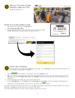
Mount the DXM Controller in a secure 
location, outside of any metal cabinets or 
enclosures.
The DXM Controller has four mounting 
holes. Use ¼-20 mounting bolts or self 
tapping screws to secure the controller to 
a rigid surface.

The Operator Interface can be mounted near each monitored door, in a central supervisory 
location, or can be held by an employee to actively monitor the occupancy level.
Mount the Operator Interface to a rigid surface using the mounting holes and  ¼-20 bolts, 
self tapping screws, or optional magnetic mounts listed at the end of this document.

How you mount your sensor varies based on the application requirements. User-provided custom mounting fixtures may be 
required in cases where the supplied brackets are not compatible with the installation location. Contact your local distributor or 
Banner Engineering’s Technical Support team at 1-800-203-5616 for more options or refer to our Troubleshooting section on page 
9.

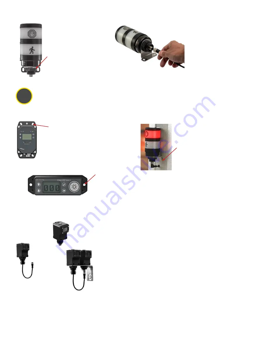
When mounting the Q45 Sensor Pairs on the inside of the door:

1.  Place Sensor A closest to the L section of the mounting bracket. 
2.  Place Sensor B on the remaining mounting hole. 
3.  Thread the black locknut onto the bases and hand tighten. 
4.  Connect the cable from Sensor B to Sensor A, aligning the key in the connector 

on the cable with the key on the connector on Sensor A. Hand tighten only.

Note: Sensor A has a 5-pin male connector on the bottom. Sensor B has the cable.

Mounting Recommendations

•  Mount the sensors at a minimum height of 40 inches (1 meter) to avoid the potential for miscounts. Mounting the sensor at a height 

below 40 inches may result in double counts by detecting arm or leg motion.

•  Mount the sensors no farther than 12 feet away from the reflectors for optimal performance. This may vary by door application/

customer need. 

•  Mount the sensors 3 inches apart from each other (center to center) when you are not using the supplied mounting brackets.

Sensor A has the 
integrated 5-pin male 
quick disconnect 
connector

Sensor B has 
the integrated 
6-inch cable 
with a female 
quick disconnect 
connector

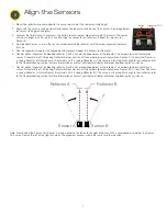
2. Connect the power supply to the 
Indicator Light, aligning the keys in the 
connector. Hand tighten.
3. Connect the power supply into a 
power outlet using the appropriate 
regional wall adapter.

Mount and Supply Power to the TL70 Wireless Indicator Light

1. Position the Indicator Light on the 
bracket so that the icons are facing 
the desired orientation. 
Secure with the supplied lock nut. 
Hand tighten only.

A

B

Summary of Contents for Q45

Page 1: ...217889 Rev A Occupancy Solution Kit Total Count TC Setup Guide ...

Page 2: ...ator includes bracket and power supply Q45 Sensor Pair includes AA batteries DXM Controller Not Shown mounted inside building Direct Select Operator Interface includes C battery Power Supply Reflector Pair pre mounted on bracket Tools Needed Tape measure Phillips screwdriver ...

Page 3: ...M Controller in a secure location outside of any metal cabinets or enclosures The Q45 Sensor Pair detects whether a person is entering or exiting the monitored area The Sensor Pair comes with two sensors Sensor A and Sensor B Mount the Q45 Sensor Pair according to Banner s suggested mounting instructions on page 6 The Direct Select Operator Interface displays the total count of people in the monit...

Page 4: ...e four corner screws Do not over tighten 5 If the indicator LEDs do not automatically begin flashing turn on the sensor by pressing and holding the button for five seconds until the LED to the right of the button flashes 1 Loosen the clamp plate with a small Phillips screwdriver and lift the cover 2 Using a small Phillips screwdriver insert the tip into the small hole in the battery holder and pry...

Page 5: ...or or Banner Engineering s Technical Support team at 1 800 203 5616 for more options or refer to our Troubleshooting section on page 9 When mounting the Q45 Sensor Pairs on the inside of the door 1 Place Sensor A closest to the L section of the mounting bracket 2 Place Sensor B on the remaining mounting hole 3 Thread the black locknut onto the bases and hand tighten 4 Connect the cable from Sensor...

Page 6: ...oors For occupancy monitoring in areas with inward opening doors Banner recommends mounting the devices on the inside of the door far enough from the door that the door does not trip the sensor pair when opening Two mounting options are shown I and II Mounting I is preferred to keep the sensors and reflectors from obstructing the area Mounting II is possible when no other mounting options are avai...

Page 7: ...s seeing Reflector B Rotate Sensor A outward until it is seeing Reflector A If the sensors will not optically align to their reflector refer to the Troubleshooting section for more information or contact your local distributor or Banner Engineering for assistance 7 Confirm optical alignment by blocking reflector B with a hand or opaque object at the reflector The amber alignment indicator on senso...

Page 8: ...Registers menu and press ENTER Highlight Occupancy Limit and press ENTER Enter your desired Occupancy Limit 1 Using the up and down arrow buttons select the first digit for the limit and press ENTER to set the first digit 2 Use the up and down arrows to set the second digit and press ENTER 3 Repeat if you are adding a third digit 4 Press ENTER once more to highlight SEND and press ENTER to confirm...

Page 9: ...r before counts are displayed The Operator Interface may not be communicating with the DXM Controller Check the LED above the check mark button If the LED flashes red change the positioning of the DXM Controller or Operator Interface so that they are closer to each other The LED should flash green when the Operator Interface is communicating to the DXM Controller If the indicator LED does not begi...

Page 10: ...f directed to by your IT department Setting a Static IP Address To define a specific IP address of your choosing 1 On the DXM use the arrows and move to the System Config menu Press ENTER 2 Use the arrow keys to select the Ethernet menu Press ENTER 3 Highlight the DHCP selection and press ENTER Set DHCP to OFF 4 The system will request a restart press ENTER to confirm 5 Follow steps 1 and 2 to ent...

Page 11: ...ler s LCD On the DXM s main menu scroll to System Info and then press ENTER twice to view the seven digit serial number at the bottom of the information list 3 Enter all seven digits into the DXM Serial entry field on Banner CDS 4 Verify that Configuration is set to Solutions and select Occupancy for the Kit Type This allows the Banner CDS application to automatically create Dashboard layouts and ...

Page 12: ...nch screw mounts Used on multiple mounting brackets 31 75 mm 1 25 inch diameter No fasteners included LMB30LP Used with the TL70 Wireless Indicator Light Low profile 30 mm mounting hole 300 series stainless steel No fasteners included SMBAMS30RA Used with the Q45 Sensor Pair one per sensor Right angle SMBAMS series bracket 30 mm hole for mounting sensors Articulation slots for 90 rotation 12 gauge...

Reviews: