Banner Q45 Setup Manual Download Page 3

3

The Occupancy Solution Kit works by monitoring the number of people into and out of an area. User defined Alert levels trigger a red 
indicator on the Operator interface and indicator light to show that the area occupancy has been exceeded. Occupancy levels reset 
automatically every night at 2 AM Central Time.
Total Count (TC) Solution Kits are configured to monitor between one and four doors out of the box. The Q45 Sensor Pairs monitor people 
entering and exiting the area, for up to four doors, and give a total count of people inside. The Operator Interface displays the number of 
people in the area and allow for employee adjustments to the occupancy count. Indicator lights display if additional people are allowed to 
enter the area or if they are required to wait until the occupancy level drops below a user-defined limit.
Multiple Count (MC) Solutions Kits are available when a user requires individual door Occupancy Limits.

The 

DXM Controller

 sets the user-defined occupancy levels. The display shows the current occupancy level 

and other system metrics.
The Occupancy Limit defines the area’s maximum capacity. The Occupancy Warning value defines a warning 
level below the Occupancy Limit to indicate when the occupancy is close to the area’s capacity. Reaching the 
Occupancy Warning value triggers faster reporting.
Set the Occupancy Warning below the Occupancy Limit.
Mount the DXM Controller in a secure location outside of any metal cabinets or enclosures.
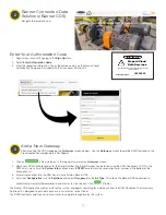
The 

Q45 Sensor Pair

 detects whether a person is 

entering or exiting the monitored area. The Sensor Pair 
comes with two sensors, Sensor A and Sensor B.
Mount the Q45 Sensor Pair according to Banner’s 
suggested mounting instructions on page 6.
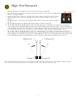
The 

Direct Select® Operator Interface

 displays the total count of people in the monitored 

area. 
The indicator is off when the occupancy level is below the warning limit. The indicator turns 
yellow when the warning limit has been reached. The indicator turns red when the Occupancy 
limit has been reached.

Use the 

 (up) and 

 (down) buttons to manually make corrections to the total count by 

increasing and decreasing the count to reflect the actual occupancy level. The display may 
take up to two seconds to update the manual adjusts. The 

 (back) button resets the entire 

system back to 0 occupancy.
The Operator Interface can be mounted near each monitored door or can be held by an 
operator to actively monitor the occupancy level.
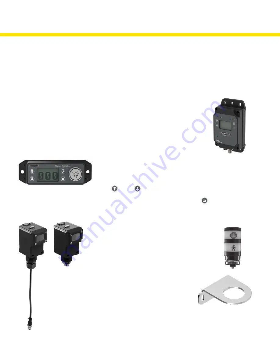
The 

Indicator Light

 alerts people when entering into 

the area is allowed (green) and when entering is no 
longer allowed (red).
An optional yellow segment can be added to display 
the Occupancy Warning.
Mount the Indicator Light indoors when possible and 
mount so that people entering the monitored area are 
able to see the occupancy status.

How it Works

Occupancy monitoring is inherently subject to irregular human movement and the system cannot be guaranteed to detect with 100% accuracy in all cases.

Indicator Light bracket, model 
LMB30LP (included with kit)

Summary of Contents for Q45

Page 1: ...217889 Rev A Occupancy Solution Kit Total Count TC Setup Guide ...

Page 2: ...ator includes bracket and power supply Q45 Sensor Pair includes AA batteries DXM Controller Not Shown mounted inside building Direct Select Operator Interface includes C battery Power Supply Reflector Pair pre mounted on bracket Tools Needed Tape measure Phillips screwdriver ...

Page 3: ...M Controller in a secure location outside of any metal cabinets or enclosures The Q45 Sensor Pair detects whether a person is entering or exiting the monitored area The Sensor Pair comes with two sensors Sensor A and Sensor B Mount the Q45 Sensor Pair according to Banner s suggested mounting instructions on page 6 The Direct Select Operator Interface displays the total count of people in the monit...

Page 4: ...e four corner screws Do not over tighten 5 If the indicator LEDs do not automatically begin flashing turn on the sensor by pressing and holding the button for five seconds until the LED to the right of the button flashes 1 Loosen the clamp plate with a small Phillips screwdriver and lift the cover 2 Using a small Phillips screwdriver insert the tip into the small hole in the battery holder and pry...

Page 5: ...or or Banner Engineering s Technical Support team at 1 800 203 5616 for more options or refer to our Troubleshooting section on page 9 When mounting the Q45 Sensor Pairs on the inside of the door 1 Place Sensor A closest to the L section of the mounting bracket 2 Place Sensor B on the remaining mounting hole 3 Thread the black locknut onto the bases and hand tighten 4 Connect the cable from Sensor...

Page 6: ...oors For occupancy monitoring in areas with inward opening doors Banner recommends mounting the devices on the inside of the door far enough from the door that the door does not trip the sensor pair when opening Two mounting options are shown I and II Mounting I is preferred to keep the sensors and reflectors from obstructing the area Mounting II is possible when no other mounting options are avai...

Page 7: ...s seeing Reflector B Rotate Sensor A outward until it is seeing Reflector A If the sensors will not optically align to their reflector refer to the Troubleshooting section for more information or contact your local distributor or Banner Engineering for assistance 7 Confirm optical alignment by blocking reflector B with a hand or opaque object at the reflector The amber alignment indicator on senso...

Page 8: ...Registers menu and press ENTER Highlight Occupancy Limit and press ENTER Enter your desired Occupancy Limit 1 Using the up and down arrow buttons select the first digit for the limit and press ENTER to set the first digit 2 Use the up and down arrows to set the second digit and press ENTER 3 Repeat if you are adding a third digit 4 Press ENTER once more to highlight SEND and press ENTER to confirm...

Page 9: ...r before counts are displayed The Operator Interface may not be communicating with the DXM Controller Check the LED above the check mark button If the LED flashes red change the positioning of the DXM Controller or Operator Interface so that they are closer to each other The LED should flash green when the Operator Interface is communicating to the DXM Controller If the indicator LED does not begi...

Page 10: ...f directed to by your IT department Setting a Static IP Address To define a specific IP address of your choosing 1 On the DXM use the arrows and move to the System Config menu Press ENTER 2 Use the arrow keys to select the Ethernet menu Press ENTER 3 Highlight the DHCP selection and press ENTER Set DHCP to OFF 4 The system will request a restart press ENTER to confirm 5 Follow steps 1 and 2 to ent...

Page 11: ...ler s LCD On the DXM s main menu scroll to System Info and then press ENTER twice to view the seven digit serial number at the bottom of the information list 3 Enter all seven digits into the DXM Serial entry field on Banner CDS 4 Verify that Configuration is set to Solutions and select Occupancy for the Kit Type This allows the Banner CDS application to automatically create Dashboard layouts and ...

Page 12: ...nch screw mounts Used on multiple mounting brackets 31 75 mm 1 25 inch diameter No fasteners included LMB30LP Used with the TL70 Wireless Indicator Light Low profile 30 mm mounting hole 300 series stainless steel No fasteners included SMBAMS30RA Used with the Q45 Sensor Pair one per sensor Right angle SMBAMS series bracket 30 mm hole for mounting sensors Articulation slots for 90 rotation 12 gauge...

Reviews: