Banner iVu PLUS TG User Manual Download Page 113

8.4.2 Assembly Objects

Outputs from PLC

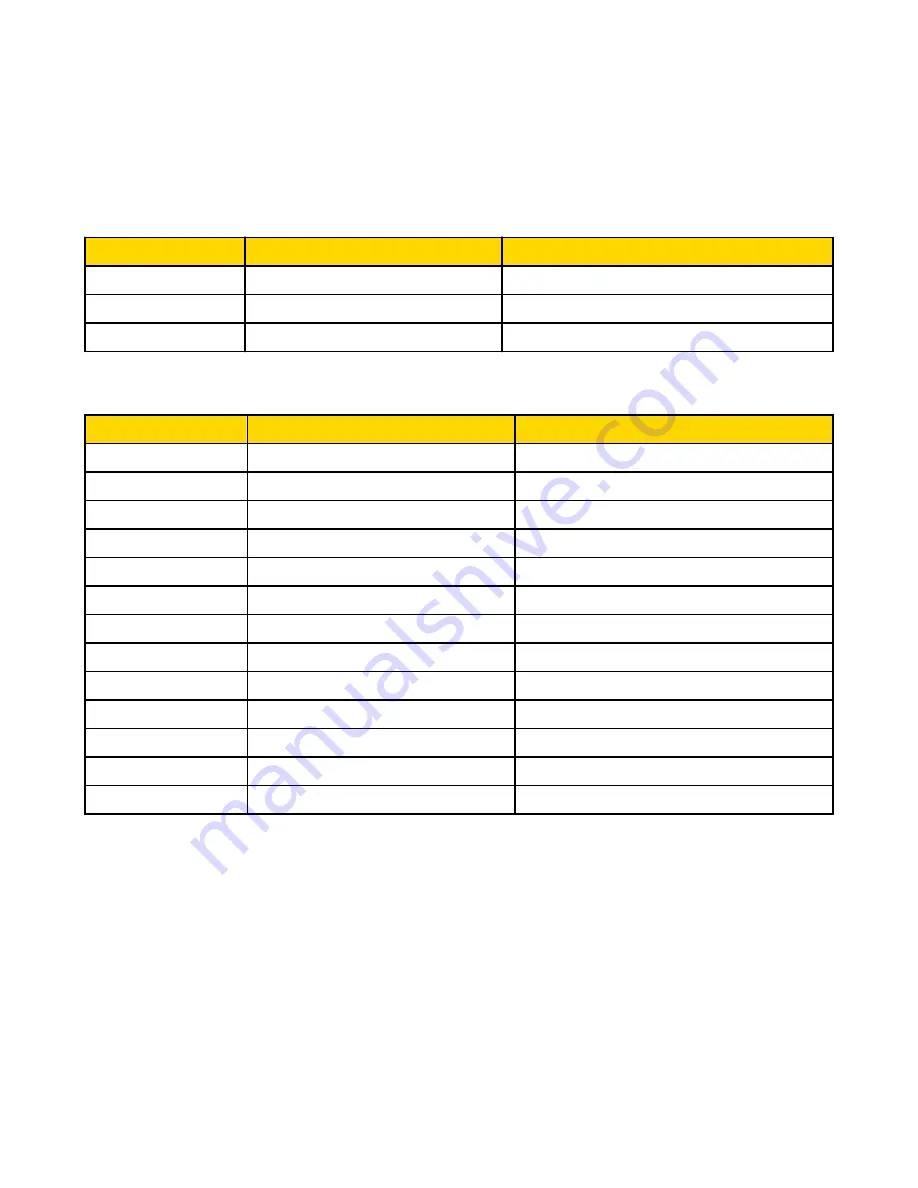
iVu_OUTPUT1 Instance 0x70 (112) - 6 Registers

WORD #

WORD NAME

DATA TYPE

0

Input Bits Register

16-bit integer

1-2

Product Change Number

32-bit integer

3-5

reserved

iVu_OUTPUT2 0x71 (113) - 240 Registers

WORD #

WORD NAME

DATA TYPE

0

Inputs Bit Register

16-bit integer

1-2

Product Change Number

32-bit integer

3-49

reserved

32-bit integer

50

Command ID

16-bit integer

51

Command Parameter Int16

16-bit integer

52-53

Command Parameter Int32

32-bit integer

54-55

Command Parameter Float

Float

56-57

String Length

32-bit integer

58-107

String Parameter

100 Byte Array

108

reserved

16-bit integer

109-110

Barcode String/Mask Length

32-bit integer

111-210

Barcode String/Mask

200 Byte Array

211-239

reserved

iVu Plus User's Manual


Online Only - rev. B

www.bannerengineering.com - tel: 763-544-3164

113

Summary of Contents for iVu PLUS TG

Page 1: ...iVu Plus User s Manual Online Only rev B 1 25 2012 ...

Page 2: ...ection 51 4 1 Selecting a Sensor Type 51 4 2 Acquiring a Good Image 52 4 3 Configuring an Area Sensor 54 4 4 Configuring a Blemish Sensor 56 4 5 Configuring a Match Sensor 58 4 5 1 Remote Teach 62 4 6 Configuring a Sort Application 62 5 iVu Plus Communications 64 5 1 iVu Plus Communications 64 5 1 1 64 5 1 2 Communication Channels 64 5 1 3 Industrial Ethernet 64 5 1 4 Command Channel 64 5 1 5 Data...

Page 3: ...on 104 8 4 2 Assembly Objects 113 8 4 3 Configuration Assembly Object 120 8 4 4 Data Formats 120 8 4 5 Minimum Requested Packet Inverval RPI Value 120 8 4 6 Sample Timing Diagram 121 8 5 Modbus TCP 125 8 5 1 Holding Registers 126 8 5 2 Output Registers 127 8 5 3 Input and Output Coils 132 8 6 PLC5 and SLC 5 PCCC 133 8 6 1 Configuration 133 8 6 2 Output Registers 135 8 6 3 Input Registers 136 8 6 4...

Page 4: ...or documentation is available in a convenient printable format PDF on the installation CD or on the Banner Web site http www bannerengineering com Banner Website The most current iVu Plus Series sensor information is available on the Banner website www bannerengineering com Warranty Service The iVu Plus Image Sensor is designed for reliability Do not open the housing it contains no field replaceab...

Page 5: ...sages that appeared on your screen A description of what you were doing and what happened A description of how you tried to solve the problem Error Codes see LED Indicator Troubleshooting on page 153 1 2 Maintenance Maintenance tasks include keeping the hardware free of dust and dirt and possibly updating the iVu firmware as new versions become available Cleaning the Sensor Regularly remove any du...

Page 6: ...nfiguration install connect iVu select sensor type acquire image set inspection parameters 68 5 mm touch screen LCD display 320 x240 pixels Choice between 3 inspection tools pattern match and area detection with or without motion compensation Robust IP67 housing with integrated lighting red blue green or infrared M12 connector with 10 to 30 VDC for power supply and PNP or NPN output External trigg...

Page 7: ...d federal regulations that make the quality of pharmaceutical packaging increasingly critical when tablets are inser ted into a blister pack manufacturers need to verify that all the blisters in a pack have been filled with unbroken tablets To verify each blister in the pack use an iVu Series sensor configured for an Area inspection The sensor inspects each blister pack to make sure that each blis...

Page 8: ...a proper seal on the glass vial If the stopper is missing or incorrectly positioned then the sensor sends a fail output to the line 2 2 Installing the Sensor 2 2 1 Installing and Connecting the Sensor The iVu Plus TG sensor requires a bracket for mounting Three brackets are available from Banner The brackets allow the sensor to be mounted either perpendicular to the part or at an adjustable angle ...

Page 9: ...t clockwise approximately 5 complete turns or until the Focusing Window disengages from the light lens assembly NOTE The light lens assembly may include an integrated ring light or a blank disk if an integrated ring light is not used Be careful that the light lens assembly does not pull out when removing the Focusing Window Give a slight tug on the Focusing Window when you think you ve unscrewed i...

Page 10: ...e available separately 1 Remove the Lens Enclosure and Lens 2 Install filter behind the retainer ring Make sure it is fully seated 3 Using the provided retainer ring tool thread the retainer ring into the sensor until it firmly seats the filter 4 Replace the Lens and Lens Enclosure on the camera CAUTION Avoid the damage that electrostatic discharget ESD can cause to the sensor Always use a proven ...

Page 11: ...ions on the iVu Plus with remote display are shown below and power I O connections B are defined in the Power I O Connections table below A B C D A Remote Display Connector B Power I O Connector C USB Connector D Ethernet Connector NOTE Microlens model shown C Mount model connections are identical iVu Plus User s Manual Online Only rev B www bannerengineering com tel 763 544 3164 11 ...

Page 12: ...tect the Trigger or Remote Teach input on the low to high transition This setting can be changed in the Main Menu System Discrete I O Input Polarity screen on the sensor iVu Low to High Trigger and Remote Teach Input Waveforms The iVu Trigger and Remote Teach input waveforms are shown below Power up Trigger Remote Teach Pink Wire Color Function Gray The sensor triggers from low to high and Remote ...

Page 13: ...s positive voltage and the sensor s input as shown below Trigger Input Remote Teach Input iVu Pullup Resistor 1k ohm NPN VCC Sinking Option 2 Enable the Input Pullup in the iVu Plus TG software Main Menu System Discrete I O Input Pullup iVu Output Waveforms PNP Outputs Ready Pass Fail Pass Pass Fail Pass Function Strobe Out Configure as External Expose Based Outputs 1 2 and 3 Set as Active Pass Ou...

Page 14: ...affect the sensor results To exit Demo Mode go to Main Menu System Sensor Mode and select Live from the drop down list When you exit Demo Mode the sensor reboots into its normal operating mode with default settings NOTE You may return to Demo Mode any time by going to Main Menu System Sensor Mode and se lecting Demo 2 3 2 Sensor Types The iVu Plus TG sensor includes four Sensor Types Area Sensor A...

Page 15: ...rt in any orientation matches a reference pattern The reference pattern is taught during setup A reference pattern might include alphanumeric characters logos or any other shapes During an inspection the sensor checks that each part or package being inspected matches the reference pattern Additionally if there is more than one of the identified pattern the number expected can be set Some example a...

Page 16: ...her Area Blemish Match or Sort 3 Click the Home Screen icon in the upper left corner of the screen to return to the Home screen iVu Plus User s Manual 16 www bannerengineering com tel 763 544 3164 Online Only rev B ...

Page 17: ... inspections of different Sensor Types Adding a New Inspection To Add a new stored inspection 1 Go Main Menu Inspection Stored Inspections and click Add New 2 Select the Sensor Type for the new inspection and click Next 3 Click Done iVu Plus User s Manual Online Only rev B www bannerengineering com tel 763 544 3164 17 ...

Page 18: ...w button in the top center of the screen that displays the currently running inspection to display all the stored inspections 2 Select the inspection to start and click the Start Running button that appears below it iVu Plus User s Manual 18 www bannerengineering com tel 763 544 3164 Online Only rev B ...

Page 19: ...ely control the iVu Plus sensor and access sensor results Industrial Ethernet a bi directional communication channel that allows the user to control the sensor and access sensor results using Ethernet IP Modbus TCP or PCCC protocol Data Export used to export selected inspection data to a remote device Image Export used to export inspection images to a remote device Data export and command channel ...

Page 20: ...tings Imager to run the Auto Exposure routine and to make adjustments to functions like exposure gain and strobe System to select the Sensor Type and to manage the device Logs to configure and view System and Inspection Logs iVu Plus User s Manual 20 www bannerengineering com tel 763 544 3164 Online Only rev B ...

Page 21: ...nsor Menus Industrial Ethernet Setup View Logs System Live Mode Demo Mode Sensor Information Sensor Mode Save to USB Load from USB Reset to Defaults Sensor Configuration Lock Sensor Serial I O Data Export Image Export Communications Connection Data to Export Output Format Input Polarity Input Pullup Output Type Output 1 Discrete I O Command Channel Connection Connection Delimiters Fail Hold Time L...

Page 22: ...vailable An Area Sensor Type that detects if a particular feature or features is present A Blemish Sensor Type that can be used find flaws on a part for example scratches on a disc It can also be used to make sure that a feature exists on a part A Match Sensor Type that determines whether a part or label match es some reference part or label A Sort Sensor Type that is used to identify and sort up ...

Page 23: ... Area sensor see Demo Mode Blemish Menu Main Menu Inspection Blemish When configured as a Blemish sensor the sensor can be used find flaws on a part for example scratches on a disc It can also be used to make sure that a feature exists on a part Although this is more commonly an application for a sensor configured as an Area sensor a Blemish sensor may be a better option to find a feature when dea...

Page 24: ...e a working example of the sensor configured as a Match sensor see Demo Mode Sort Tool Menu Options Main Menu Inspection Sort The Sort tool is used to identify and sort up to 10 stored patterns The menu items in the Sort tool provide for managing stored patterns and configuring Sort tool inspection parameters iVu Plus User s Manual 24 www bannerengineering com tel 763 544 3164 Online Only rev B ...

Page 25: ...of time If this value is set too high the sensor can miss triggers while trying to detect a bad pattern Stored Inspections Menu Main Menu Inspection Stored Inspections Stored Inspections is used to manage stored inspections Management of stored inspections includes adding deleting and specifying which inspection should be defined as the Startup inspection iVu Plus User s Manual Online Only rev B w...

Page 26: ...running When adding a new inspection the Sensor Type and inspection name will be set Select Running Inspection Screen Main Menu Inspection Stored Inspections Select This screen is used to select a new running inspection Select the name of the inspection to start and click the Start Running button that displays iVu Plus User s Manual 26 www bannerengineering com tel 763 544 3164 Online Only rev B ...

Page 27: ... as the Startup inspection then click on the Set as Startup button that displays Motion Menu Main Menu Inspection Motion Enable Motion when the part is expected to move or rotate Motion settings also involve selecting the number of edges to locate adjusting sensitivity and selecting whether or not rotation is enabled These settings appear on the Inspection Menu after Motion is set to Enabled iVu P...

Page 28: ...o finding a reference edge The Sensitivity value helps ac count for light variations that might affect how well the sensor detects edges on inspected parts The Sensitivity scale is from 0 to 100 where 0 means least sensitive and 100 means most sensitive If set near 0 the sensor will only find very sharp edges with strong contrast If set near 100 the sensor will find very dim or blurry edges and ma...

Page 29: ...ection if Two Edges is selected motion can be tracked horizontally and vertically ROI Type Screen A Region of Interest ROI is a user defined area to be analyzed in the sensor s field of view An ROI can be rectangu lar elliptical or circular and resized as appropriate for the application iVu Plus User s Manual Online Only rev B www bannerengineering com tel 763 544 3164 29 ...

Page 30: ...posure and Gain set Trigger and Strobe options as well as the size of the field of view FOV Auto Exposure Screen Main Menu Imager Auto Exposure Auto Exposure optimizes the exposure time and gain for the current inspection Exposure Screen iVu Plus User s Manual 30 www bannerengineering com tel 763 544 3164 Online Only rev B ...

Page 31: ...e image External Strobe Screen Main Menu Imager Strobe External The External Strobe is a 5V output that can be used for an external light Setting options are Always ON Always OFF or Exposure Based If Exposure Based is selected then the external light is on during the time the sensor is capturing an image Focus Screen Main Menu Imager Focus iVu Plus User s Manual Online Only rev B www bannerenginee...

Page 32: ...similar over time FOV Menu Main Menu Imager FOV The field of view FOV is the area that the sensor can see at the working distance The working distance is the dis tance from the sensor s lens cover to the part being inspected By default the field of view FOV is the entire sensor display The FOV can be reduced in order to speed up the processing time of an inspection or to decrease background noise ...

Page 33: ... an inspection or to decrease background noise Gain Screen Main Menu Imager Gain Gain is an electronic boost to the image signal Increasing Gain by using the right arrow key or moving the slider to the right increases image brightness without increasing exposure time Note that Gain brightens both the light pixels and dark pixels and may reduce the image quality Internal Strobe Screen Main Menu Ima...

Page 34: ...g light The External Strobe configures the operation of an external light Trigger Screen Main Menu Imager Trigger A Trigger is a signal that makes the sensor capture an image and inspect it Use the radio buttons to select either External Trigger Internal Trigger Free Run or Command If Internal Trigger is selected triggers are based on timed intervals and you need to select a trigger interval betwe...

Page 35: ...hannel is used to trigger the sensor from a remote device When Industri al Ethernet Only is selected trigger commands from the Industrial Ethernet communications channel only will be accep ted 3 4 System Menu System Menu Main Menu System The System menu provides for selecting Sensor Mode updating sensor firmware backing up and restoring sensor Configuration and other general system level operation...

Page 36: ...ications The Communications menu is used to configure iVu communications This includes configuring Ethernet and or Serial I O ports configuring up to three communications channels one for data export another for image export and another as a command channel which is for bi drectional communications NOTE The iVu Plus supports up to three communications channels on a sen sor but only one of the chan...

Page 37: ...spection data when triggered Data Export To Export Screen Main Menu System Communications Data Export Data To Export The Data To Export screen is used to determine the information included in a data export Data will output in the order displayed on the screen iVu Plus User s Manual Online Only rev B www bannerengineering com tel 763 544 3164 37 ...

Page 38: ...nd none of the changes you make will be saved To exit Demo Mode select Exit Demo Mode You may exit this mode later by selecting Main Menu System Sensor Mode and select Live When you exit Demo Mode the sensor reboots into its normal operating mode Note You may return to Demo Mode any time by going to Main Menu System Sensor Mode and selecting Demo Sensor Configuration Menu Main Menu System Sensor C...

Page 39: ... to USB screen provides for saving sensor Configuration to a USB flash drive The saved configuration infor mation can be used as a backup or as a way to clone configuration information for other sensors Load from USB Main Menu System Sensor Configuration Load from USB The Load from USB screen provides for restoring sensor Configuration from a USB drive Ethernet I O Screen Main Menu System Communic...

Page 40: ... sensor is producing export data frames faster than the data can be exported from the device due to bandwidth limita tions or faster than the client is reading the channel export data This setting affects how the sensor will behave in this situation Select Hold READY to ensure that all frames are transmitted In this case the READY signal will remain inactive sensor is busy until the new frame has ...

Page 41: ...to process any triggers and the inspection will continue normally This time delay is just for the screen You can set this parameter using the slider at the bottom of the screen Firmware Update Screen Main Menu System Firmware Update The Firmware Update screen is used to load the latest sensor firmware The Firmware Update screen lists the firmware versions it finds in the BANNER FIRMWARE folder on ...

Page 42: ...igh To Low The Trigger and Remote Teach are detected on a high to low transition of the signal Input Pullup Screen Main Menu System Discrete I O Input Pullup By default the Input Pullup is disabled If the device used to trigger and remote teach the iVu sensor is a Sinking device NPN then you will only need to enable Input Pullup here if that device does not have its own pullup resistor Other wise ...

Page 43: ... be 4 digits entered using the software keypad If the password is lost use the Password Reset Utility software provided in the CD to obtain a Reset Key Output1 Screen Main Menu System Discrete I O Output1 Output 1 can be configured for Pass Fail Sort Pattern 1 Missed Trigger or System Error The default setting is Pass and Latched for this output For Latched the signal is active until the results o...

Page 44: ...red for Pass Fail or Sort Pattern 3 The default setting is Pass and Latched for this output For Latched the signal is active until the results of an inspection cause a change in the signal output If Pulse is selec ted the default Pulse width is 50 ms Port Errors Main Menu System Port Status The Port Errors screen can help to debug communications channel issues Parity Break and Framing indicate mis...

Page 45: ...nspections on stored images This mode demonstrates how the sensor is set up without having to worry about focus lighting or triggers In this mode you can learn how to make adjustments while ob serving how the adjustments affect the inspections Note that this mode is just for demonstration and none of the changes you make will be saved To exit Demo Mode select Live Serial I O Settings Main Menu Sys...

Page 46: ... Users can still monitor pass fail statistics as well as access logs and save logs to a USB device When the sensor is locked a lock appears in the upper left corner of the LCD You can lock the sensor with or without a password Passwords are 4 digits in any combination and you can reset the password at any time If you forget the password the system will display a device ID which you need to use wit...

Page 47: ...Log The iVuPlus device can be controlled or monitored over Industrial Ethernet using Ethernet IP Modbus TCP or PCCC protocols This document will help you to set up the iVu Plus in the desired configuration and provide you with informa tion you will need to connect to the master device PLC HMI etc Command Channel Log Main Menu Logs Communication Logs Command Channel iVu Plus User s Manual Online On...

Page 48: ...e display and clearing the log Additionally the communication log can be saved to the USB drive so that the communica tion log can be imported to the emulator Image Export Channel Log Main Menu Logs Communication Logs Image Export The Image Export log is purely an an output log so there is no receive input activity Image Export is only available over Ethernet When a user enables Image Export the l...

Page 49: ...ion Up to ten Inspection Logs can be held in memory on the sensor The next ten overwrite the previous Inspection Logs can be saved to the USB drive so that the logs can be imported to the emulator Inspection Logs Setup Screen Main Menu Logs Inspection Logs Setup Use the radio buttons to Disable Logging or to log Passed Inspections Failed Inspections or All Inspections iVu Plus User s Manual Online...

Page 50: ...ogs System Logs System Log The System Log contains configuration change information other notifications and any errors or warnings that may be encountered The list is sorted in descending order with respect to time The Time associated with each event consists of the Hour Count lifetime hours of operation and the Up Timer time elapsed since last boot Click the icon in the upper left corner of the s...

Page 51: ... Demo Mode the sensor reboots with a single inspection with a Match sensor type by default To change the Sensor Type 1 Go to Main Menu Inspection Properties Sensor Type This displays the Sensor Type menu options 2 Select either Area Blemish Match or Sort 3 Click the Home Screen icon in the upper left corner of the screen to return to the Home screen Online Only rev B www bannerengineering com tel ...

Page 52: ...ackground Depending on the target this may mean the integral ring light is not the best choice and other Banner lights should be consid ered Adjust the mounting angle to provide the clearest image of the part features you are monitoring The mounting bracket lets you easily position and adjust the sensor on your line 3 If needed go to Main Menu Imager Auto Exposure to run the Auto Exposure routine ...

Page 53: ...ge has been acquired lock the focusing window Micro Lens Models A Lens B Focusing Window C Locking Clip D Locking Screw E Filter Cap optional F Filter optional NOTE Filter Kits are available separately For C Mount Models Only 1 Remove the Lens Enclosure 2 Adjust focus while monitoring the focus number To ensure the best image adjust the focus until the Focus Number peaks 3 Replace the Lens Enclosu...

Page 54: ...ernal trigger input Use the Trigger icon in the lower right of the screen to manually trigger the sensor to capture an image as you set up and test Capture images of a range of samples to set up from the worst good part to the best bad part Start the setup with a good part Normally each part to be tested will be centered in the Field of View FOV 1 Adjust the Region of Interest ROI The ROI is a blu...

Page 55: ...ntensity Range option 2 Click on the eye dropper icon on the left of the screen and then click anywhere in one of the white letters Now any white area will be highlighted in green Use the slider bar at the bottom of the display to fine tune the selection As the slider bar is moved green highlighted areas indicate objects the sensor finds and counts The objects colored yellow are found but filtered...

Page 56: ...s to make sure that the sensor accepts good parts and rejects bad 7 To complete the Area application setup set triggering as appropriate for your application NOTE Remote Teach does not work with the Area Sensor type 4 4 Configuring a Blemish Sensor This section describes how to configure a Blemish sensor using the Demo application as a reference The Demo application shows how the sensor when confi...

Page 57: ... inspection parameters Adjust the Sensitivity parameter 1 Go to Main Menu Inspection and click the Sensitivity option 2 Use the slider on the bottom of the screen to adjust the sensitivity watching as the sensor detects more or fewer edges 3 Click the Trigger button on the bottom right of the screen to see how the sensor detects edges on other images and adjust if necessary Adjust the Edge Length ...

Page 58: ... Menu Inspection and click the Pass Count option 2 Use the brackets to set a tolerance for the pass fail 4 Test the complete range of good and bad samples to make sure that the sensor accepts good parts and rejects bad 5 To complete the Blemish application setup set triggering as appropriate for your application NOTE Remote Teach does not work with the Blemish Sensor type 4 5 Configuring a Match S...

Page 59: ...to set up from the worst good part to the best bad part Start the setup with a good part Normally each part to be tested will be centered in the Field of View FOV 1 Teach the sensor a good reference part a Adjust the Region of Interest ROI The ROI is a blue dotted box as shown below b Click Anywhere within the ROI to select it When selected the ROI is red with resize and rotational icons in the co...

Page 60: ... below the specified value for Percent Match down to approximately 20 or out of the Rota tion Range see below will be colored yellow 1 Using a bad part click the Manual Trigger icon in the lower right of the screen to capture an image For this example one of the stored images is missing the letter N yet the sensor initially sees this as a good label 2 Go to Main Menu Inspection and click the Perce...

Page 61: ...that a label is correctly applied to a container that is on straight you will want to set a small rotation If you want to make sure that the correct label is present no matter how the part is oriented in the Field of View then the rotation range will be set to its maximum 180 which is the setting for the Demo Set the Pass Count parameter 1 Go to Main Menu Inspection and click the Pass Count option...

Page 62: ... Application This section describes how to configure a Sort application using the Demo application as a reference NOTE By default the Trigger is set to Internal and will continously trigger based on a time interval setting This may make it more difficult to make adjustments while setting up the sensor The best practice is as fol lows Go to the Main Menu Imager Trigger menu and select External Make...

Page 63: ...ceed the value specified for Percent Match Patterns that are within the specified Rotation Range and within approximately 20 below the speci fied value for Percent Match will be colored yellow The Rotation Range sets the expected rotation of parts or labels during an inspection For example a value of 45 means that the part may rotate 45 degrees in either direction from the reference part and still...

Page 64: ...sensor and access sensor results using Ethernet IP Modbus TCP or PCCC protocol Data Export used to export selected inspection data to a remote device Image Export used to export inspection images to a remote device Data export and command channel can be configured for either Ethernet or Serial I O but not both image export is only available over Ethernet The table below briefly summarizes valid co...

Page 65: ...rol discrete I O such as trigger and teach Get sensor results such as sensor status Change the running inspection 5 1 4 Command Channel Sample Application The iVu Plus TG installation CD has a Command Channel sample application that provides an easy interface to execute commands In a production environment you will need to create your own application for bi directional communication with the senso...

Page 66: ...ace Inspection data that can be exported includes Pass Fail Output Inspection Name Inspection Results Frame Inspection Time ms 5 1 5 Inspection Results Options Sensor Type Data to Export Area Count Area Range Blemish Count Edge Length Range Match Count iVu Plus User s Manual 66 www bannerengineering com tel 763 544 3164 Online Only rev B ...

Page 67: ...rn Names Data export settings apply to all inspections sensor wide If items are selected that are not part of the current inspection those items are ignored 5 1 5 Sample Application The iVu Plus TG installation CD has a Data Export sample application that provides for viewing exported data while setting up the sensor etc In a production environment you will need to create your own application to p...

Page 68: ...4 UInt32 Number of bytes Windows BMP image 24 27 Image Frame Number 4 UInt32 Most recently snapped image frame number 28 29 Image Width 2 UInt16 320 max 30 31 Image Height 2 UInt16 240 max 32 33 Image Format 2 UInt16 0 Bitmap 1 JPEG 34 63 Reserved 32 byte Reserved for future use NOTE If FOV s are adjusted so that they are smaller the bitmaps will also be smaller 5 1 6 Image Export Sample Applicati...

Page 69: ...the dialog click on Internet Protocol TCP IP and click the Properties button 1 Open Network Connections by clicking on the Start button then selecting the Control Panel followed by Network and In ternet and clicking Manage network connections 2 Right click the connection you want to change then click Properties If you are prompted for an administrator pass word or confirmation type the password or...

Page 70: ...0 4 In the Internet Protocol TCP IPv4 Properties dialog se lect Use the following IP address and make sure that the IP address is 192 168 0 2 and the subnet mask is 255 255 255 0 On the iVu sensor 1 Go to Main Menu System Communications Ethernet I O and make sure that the sensor is configured as shown below iVu Plus User s Manual 70 www bannerengineering com tel 763 544 3164 Online Only rev B ...

Page 71: ...mmunications Command Channel Connection and select Ethernet IP Port 32000 b Configure the field and end of frame delimiters Go to Main Menu System Communications Command Channel Delimiters iVu Plus User s Manual Online Only rev B www bannerengineering com tel 763 544 3164 71 ...

Page 72: ...y 3 To enable Data Export over Ethernet a Go to Main Menu System Communications Data Export Connection and select Serial I O from the drop down b Go to Main Menu System Communications Data Export Data To Export and select the inspection data to export iVu Plus User s Manual 72 www bannerengineering com tel 763 544 3164 Online Only rev B ...

Page 73: ...cations Data Export Output Format and select the Start String Delimiter and End String d Go to Main Menu System Communications Data Export Advanced iVu Plus User s Manual Online Only rev B www bannerengineering com tel 763 544 3164 73 ...

Page 74: ...ly after the current inspection is complete In this case the discarded frames will not be trans mitted Communications Channel Ports The following are the default Ethernet port settings for the communications channels Command Channel 32200 Data Export 32100 Image Export 32000 5 2 2 Setting Up Serial Communications The general flow for setting up for serial communications 1 Prepare the connection RS...

Page 75: ... Go to Main Menu System Communications Command Channel Delimiters Valid end of frame delimiters are comma colon semicolon CR CR LF LF CR or ETX c Optionally if you want to trigger the iVu from the control device set the trigger mode to Command go to Main Menu Imager Trigger and select Command from the drop down iVu Plus User s Manual Online Only rev B www bannerengineering com tel 763 544 3164 75 ...

Page 76: ...ection a Go to Main Menu System Communications Data Export Connection and select Serial I O from the drop down b Go to Main Menu System Communications Data Export Data To Export and select the inspection data to export iVu Plus User s Manual 76 www bannerengineering com tel 763 544 3164 Online Only rev B ...

Page 77: ...cations Data Export Output Format and select the Start String Delimiter and End String d Go to Main Menu System Communications Data Export Advanced iVu Plus User s Manual Online Only rev B www bannerengineering com tel 763 544 3164 77 ...

Page 78: ...Select Hold READY to ensure that all frames are transmitted In this case the READY signal will remain inactive sensor is busy until the new frame has been added to the channel for transmission Triggers might be missed during this time Select Do not hold READY to cause the sensor to discard the new frame if the channel is full and thus activate the READY signal immediately after the current inspect...

Page 79: ...ntry To save the log click the save icon The saved communication log can be loaded into the emulator for troubleshooting offline The table below describes the icons used in the Communication Log the up arrow indicates an incoming request to the iVu from the control device the down arrow indicates an outgoing response from the iVu to the control device Icon Description Port opened Port closed Indic...

Page 80: ... been correctly set up In addition to determining if the link has been established incoming and outgoing traffic can be monitored 6 3 Serial I O 6 3 1 Using the Port Status Screen for Testing RS 232 Communications The Port Status screen can be used to ensure data is entering and exiting the sensor This can be useful for debugging issues such as improper wiring mismatched baud rates or other serial...

Page 81: ...tallation CD or to use a terminal program running on a PC If using a terminal program in the terminal program s configuration Set new line transmit to CR LF and set the end of frame delimiters on the iVu to match Enable local echo Set the Serial port set up so that the PC port number s baud rate data parity and stop bits match those setup on the iVu 6 3 3 Verifying Basic Receive Functionality To v...

Page 82: ...are too many or too few then the port settings for example baud rate are likely mismatched in a way that does not generate serial hardware errors Verify the settings on both devices match exactly Verifying Basic Transmit Functionality The iVu command channel will only send response frames to the requesting device if it receives a valid end of frame delimiter from the requesting device To verify tr...

Page 83: ...ings on both devices match exactly If no bytes are received re check the wiring If the correct response frame is received then basic electrical and port settings are correct iVu Plus User s Manual Online Only rev B www bannerengineering com tel 763 544 3164 83 ...

Page 84: ...ntifies the data that must be set for the specified group item Note Item is not used with get commands EOF Identifies the end of frame for the command so that the iVu knows to begin processing The iVu will return a response that includes the end of frame delimiter The options for the EOF are set in the iVu Serial I O menu and are as follows comma colon semicolon CR CR LF LF CR ETX NOTE When data i...

Page 85: ...ks 7 1 3 Command Channel Command Synopsis There are a number of general types of commands to do set and get sensor data Command Channel Response Frames The iVu responds to all request frames with one or two responses depending on the type of command Do commands All do commands are followed by one response that identifies the command status For example do trigger x0D x0A OK x0D x0A Get commands All...

Page 86: ...w These are only used to make the documentation clearer get info companyname x0D x0A OK x0D x0A Banner Engineering Corp x0D x0A 7 3 Examples 7 3 1 Example 1 How to Trigger the Sensor and Retrieve Inspection Data using the Com mand Channel This example is based on a sort inspection To trigger the sensor and retrieve inspection data do the following 1 Make sure that the Command Channel is enabled us...

Page 87: ...ommand Group Item Description Get Info CompanyName The company name as a string Get Info ModelNumber The sensor model number as a string Get Info FirmwareVersion The sensor firmware version as a string Get Info SerialNumber The sensor serial number as a string Get Info Name The sensor name as a string Get Info BootNumber The number of sensor bootups Get Info UpTimer The elapsed time the sensor has...

Page 88: ...ernet SubnetMask Get the current active subnet mask of the sensor as a string Get Ethernet Gateway Get the current active Gateway ad dress of the sensor as a string Set Ethernet IPAddress Set IP address of the sensor A valid IP address must be supplied as a string for example 192 168 0 1 A Reboot command from the command channel must follow in order to make the new IP address effective You may als...

Page 89: ...ears the system error LED and sets the internal flag to false Examples get status ready x0D x0A OK x0D x0A True x0D x0A get status systemerror x0D x0A OK x0D x0A False x0D x0A do status clearsystemerror x0D x0A OK x0D x0A 7 4 Trigger Command Group Command Group Item Description Get Trigger Mode Sets trigger mode to one of the valid trigger modes for the sen sor Set Trigger Mode Sets trigger mode t...

Page 90: ...ally brighten all image pixels This value can be modi fied using the sensor s touchscreen This remotely modified value is not persisted to the sensors permanent mem ory The Save operation is re quired to persist this value Get Imager Exposure The sensor s value used to con trol the amount of time the im ager is allowed to gather light for the image This value can be modified using the sensor s tou...

Page 91: ...n on the next trigger This command can be performed using the sensor s touchscreen Examples do teach x0D x0A OK x0D x0A 7 4 ProductChange Command Group Command Group Item Description Do ProductChange Name Forces the sensor to switch to the specified inspection The sensor does not transmit a re sponse until the sensor has completed the action Inspec tions results will be invalid until the next trig...

Page 92: ...tionTime The maximum elapsed time msec of the inspection Do History Clear Clears all history fields for ex ample pass fail tool history etc Examples get history passed x0D x0A OK x0D x0A 13 x0D x0A get history startframenumber x0D x0A OK x0D x0A 3 x0D x0A do history clear x0D x0A OK x0D x0A 7 4 Inspection Command Group Command Group Item Description Get Inspection Status This status of the most re...

Page 93: ... MinArea The size of the smallest detec ted area Get AREA_RESULT MaxArea The size of the largest detected area Examples get area_result count x0D x0A OK x0D x0A 2 x0D x0A get area_result minarea x0D x0A OK x0D x0A 7665 x0D x0A 7 4 AREA_HISTORY Command Group Command Group Item Description Get AREA_HISTORY MinCount The minimum number of detec ted areas since history was last cleared Get AREA_HISTORY...

Page 94: ... blem ishes Get BLEMISH_RESULT MinEdgeLength The minimum detected blemish edge length Get BLEMISH_RESULT MaxEdgeLength The maximum detected blemish edge length Examples get blemish_result count x0D x0A OK x0D x0A 4 x0D x0A get blemish_result minedgelength x0D x0A OK x0D x0A 22 x0D x0A 7 4 BLEMISH_HISTORY Command Group Command Group Item Description Get BLEMISH_HISTORY MinCount The minimum number o...

Page 95: ...ount The number of detected match es Get MATCH_RESULT MinPercentMatch The minimum detected match percentage Get MATCH_RESULT MaxPercentMatch The maximum detected match percentage Examples get match_result count x0D x0A OK x0D x0A 1 x0D x0A get match_result maxpercentmatch x0D x0A OK x0D x0A 6 x0D x0A 7 4 MATCH_HISTORY Command Group Command Group Item Description Get MATCH_HISTORY MinCount The mini...

Page 96: ... Count The number of detected sort patterns Get SORT_RESULT MinPercentMatch The minimum detected sort pat tern match percentage Get SORT_RESULT MaxPercentMatch The maximum detected sort pattern match percentage Get SORT_RESULT PatternNumbers Listing of detected patterns by pattern number Get SORT_RESULT PatternNames Listing of detected patterns by pattern name Examples 7 4 SORT_HISTORY Command Gro...

Page 97: ... a command any arguments and an end of frame delim iter 10001 COMMAND_NOT_RECOGNIZED The command specified is not recognized 10100 GROUP_MISSING A Group ID must be specified immediately after the command 10101 GROUP_NOT_FOUND The specified Group ID is invalid unknown 10102 GROUP_ITEM_MISSING A Group Item ID must be specified immedi ately after the Group ID 10103 GROUP_ITEM_NOT_FOUND The specified ...

Page 98: ...eds maximum allowable length 20200 NO_AREAS_FOUND Attempt to obtain value when no areas were found 20600 NO_MATCHES_FOUND Attempt to obtain value when no matches were found 20800 NO_MATCHES_FOUND Attempt to obtain value when no sort pat terns were found 80000 REMOTE_DISPLAY_NOT_CONNECTED Remote Display must be connected to ob tain this value 80001 REMOTE_DISPLAY_NOT_SUPPORTED This sensor does not ...

Page 99: ...ADY state to per form a product change 80401 PRODUCT_CHANGE_INVALID_INSPEC TION Attempt to product change to a unknown or invalid inspection 80402 PRODUCT_CHANGE_TIMEOUT The Product Change operation timed out 80403 PRODUCT_CHANGE_TO_SAME_IN SPECTION Attemp to product change to the same in spection iVu Plus User s Manual Online Only rev B www bannerengineering com tel 763 544 3164 99 ...

Page 100: ...on about an established connection can be obtained from Main Menu System Communications Industrial Ethernet Status screen Click on the connection of interest to view details This device provides extensive logging for the communication that occurs over the Industrial Ethernet connection Logs can either be viewed from Main Menu System Communications Industrial Ethernet View Logs or Main Menu Logs Co...

Page 101: ...can be controlled through input bits and commands Input Bits The following commands can only be executed using bits Input Coil Bit Command Description 0 Product Change Execute a product change inspection number specified in the Product Change Num ber 32 bit integer register 1 Teach Latch Latch a teach flag Teach is executed on next trigger 2 Trigger Causes system to trigger an inspection if ready ...

Page 102: ...em error LED and resets the in ternal system error flag to false N A System Reboot Sensor 101 This command reboots the sensor If sensor configuration data is being currently being saved this command will block until that operation completes N A Save Configuration 102 This command saves all modified inspection and configuration parameters This command blocks until all values have been persisted N A...

Page 103: ...s the ACK flag when the corresponding action is complete Command flags cause actions to occur on the low to high transition of that flag You must clear the flag after the corre sponding ACK flag has been observed to be high As an example to use the Trigger ACK flag the programming steps for triggering an inspection would be 1 Wait for ready 2 Set Trigger command flag to 1 3 Wait for Trigger ACK to...

Page 104: ...t bit is cleared when all ACK bits get cleared or a new valid command is received 8 4 Ethernet IP The iVu Plus device is controlled by a ControlLogix PLC using assembly objects From the point of view of a PLC there are three input assemblies IVU_INPUT1 IVU_INPUT2 and IVU_INPUT3 and two output assemblies IVU_OUTPUT1 IVU_OUTPUT2 8 4 1 RSLogix5000 Configuration To create an implicit Class 1 configura...

Page 105: ...iVu Plus User s Manual Online Only rev B www bannerengineering com tel 763 544 3164 105 ...

Page 106: ...2 Select Module iVu Plus User s Manual 106 www bannerengineering com tel 763 544 3164 Online Only rev B ...

Page 107: ...operties See Assembly Objects on page 113 for more information on each specific assembly instance Input Assembly 100 Input Assembly 101 iVu Plus User s Manual Online Only rev B www bannerengineering com tel 763 544 3164 107 ...

Page 108: ... deselect Unicast Connection as desired NOTE The data type in the Comm Format must be changed to an INT NOTE The minimum allowed RPI is 50 ms iVu Plus User s Manual 108 www bannerengineering com tel 763 544 3164 Online Only rev B ...

Page 109: ...guration was not successful the RSLogix 5000 software will indicate errors similar to the ones displayed below ERROR Assembly Instance number and or size incorrect ERROR iVu Plus not powered up or ethernet cable not attached iVu Plus User s Manual Online Only rev B www bannerengineering com tel 763 544 3164 109 ...

Page 110: ...up from Banner module to PLC memory map C Configuration not used I Inputs to PLC outputs from iVu Plus O Outputs from PLC inputs to iVu Plus iVu Plus User s Manual 110 www bannerengineering com tel 763 544 3164 Online Only rev B ...

Page 111: ...The iVu Plus memory map expanded I Inputs to PLC outputs from iVu Plus iVu Plus User s Manual Online Only rev B www bannerengineering com tel 763 544 3164 111 ...

Page 112: ...nsor Memory Map Style changed to ASCII All data is initially transferred as INT data type An ASCII string looks like gibberish in this format Changing the style to ASCII instead of Decimal reveals the correct string data iVu Plus User s Manual 112 www bannerengineering com tel 763 544 3164 Online Only rev B ...

Page 113: ...Change Number 32 bit integer 3 49 reserved 32 bit integer 50 Command ID 16 bit integer 51 Command Parameter Int16 16 bit integer 52 53 Command Parameter Int32 32 bit integer 54 55 Command Parameter Float Float 56 57 String Length 32 bit integer 58 107 String Parameter 100 Byte Array 108 reserved 16 bit integer 109 110 Barcode String Mask Length 32 bit integer 111 210 Barcode String Mask 200 Byte A...

Page 114: ...ber 32 bit integer 6 7 Iteration Count 32 bit integer 8 9 Pass Count 32 bit integer 10 11 Fail Count 32 bit integer 12 13 Missed Triggers 32 bit integer 14 15 Current Inspection Time Float 16 29 reserved 30 52 Inspection Name 2 Word Length 40 unicode chars 53 54 Frame Number 32 bit integer WORD WORD NAME DATA TYPE 55 Sensor Type ID 16 bit integer 56 57 Area Count 32 bit integer 58 59 Area Range Mi...

Page 115: ...179 228 Command Response Data 100 Byte Array 229 239 reserved Sensor Type Match iVu Plus TG WORD WORD NAME DATA TYPE 0 Input Bits ACK Register 16 bit integer 1 Output Bits Register 16 bit integer 2 3 Error Code 32 bit integer 4 5 Inspection Number 32 bit integer 6 7 Iteration Count 32 bit integer 8 9 Pass Count 32 bit integer 10 11 Fail Count 32 bit integer 12 13 Missed Triggers 32 bit integer 14 ...

Page 116: ...t Pattern 2 Count 16 bit integer 60 Sort Pattern 3 Count 16 bit integer 61 Sort Pattern 4 Count 16 bit integer WORD WORD NAME DATA TYPE 62 Sort Pattern 5 Count 16 bit integer 63 Sort Pattern 6 Count 16 bit integer 64 Sort Pattern 7 Count 16 bit integer 65 Sort Pattern 8 Count 16 bit integer 66 Sort Pattern 9 Count 16 bit integer 67 Sort Pattern 10 Count 16 bit integer 68 Sort Min Percent Match 16 ...

Page 117: ...r 55 Sensor Type ID 16 bit integer 55 Sensor Type ID 16 bit integer 56 Barcode Count 16 bit integer WORD WORD NAME DATA TYPE 57 Barcode 1 Type 16 bit integer 58 Barcode 1 Actual Decoded Data Length 16 bit integer 59 60 Barcode 1 Data Array Length 32 bit integer 61 162 Barcode 1 Data Array 100 Byte Array 163 170 reserved 171 Command Status 16 bit integer 172 Command Response Int16 16 bit integer 17...

Page 118: ...rray 91 Barcode 4 Type 16 bit integer 92 Barcode 4 Length 16 bit integer 93 110 Barcode 4 Data 32 bit length 32 byte array WORD WORD NAME DATA TYPE 111 Barcode 5 Type 16 bit integer 112 Barcode 5 Length 16 bit integer 113 130 Barcode 5 Data 32 bit length 32 byte array 131 Barcode 6 Type 16 bit integer 132 Barcode 6 Length 16 bit integer 133 150 Barcode 6 Data 32 bit length 32 byte array 151 Barcod...

Page 119: ...nd Set BCR Mask Set BCR String Trigger Teach Latch Product Change Gated Trigger Bit Position 1 2 3 4 5 6 7 8 9 10 11 12 13 14 15 0 Input Bit Flags Execution Error System Error Teach Error Missed Trigger Output 3 Output 2 Output 1 Read No Read Pass Fail Ready Latch Ready Bit Position 1 2 3 4 5 6 7 8 9 10 11 12 13 14 15 0 iVu Plus User s Manual Online Only rev B www bannerengineering com tel 763 544...

Page 120: ...s stored first then the most significant word This format is used for Allen Bradley ControlLogix PLCs The string format is compatible with the Allen Bradley ControlLogix built in string data type This format is a 32 bit DINT length followed by character bytes SINT This results in the following string format as viewed from the iVu Plus 8 4 5 Minimum Requested Packet Inverval RPI Value iVuPlus devic...

Page 121: ...e ACK 0 Ready Product Change ProductChange ACK 1 New inspection is loaded RPI 0 1 X X Y X Y Z Product Change ACK Set ProductChange 1 Verify Ready 1 ProductChange ACK 0 Set ProductChange 0 Product Change iVu Plus User s Manual Online Only rev B www bannerengineering com tel 763 544 3164 121 ...

Page 122: ...TeachLatch ACK 1 Teach will execute on next trigger RPI 0 1 X X Y X Y Z Teach Latch ACK Set TeachLatch 1 Verify Ready 1 TeachLatchACK 0 Set TeachLatch 0 Teach Latch iVu Plus User s Manual 122 www bannerengineering com tel 763 544 3164 Online Only rev B ...

Page 123: ...K 0 Ready Trigger TriggerACK 1 Read Results Set Trigger 0 RPI 0 1 X X Y X Y Z TriggerACK Set Trigger 1 Verify Ready 1 TriggerACK 0 Trigger iVu Plus User s Manual Online Only rev B www bannerengineering com tel 763 544 3164 123 ...

Page 124: ...PI 0 1 X X Y X Y Z M N Gated Trigger ACK Set GatedTrigger 1 Verify Ready 1 TriggerACK 0 Set GatedTrigger 0 Set GatedTrigger 1 Set GatedTrigger 0 Abort Inspection could not be completed Gated Trigger iVu Plus User s Manual 124 www bannerengineering com tel 763 544 3164 Online Only rev B ...

Page 125: ...register get set when the action is complete The Status Coil register provides status of certain system states By specification Modbus TCP uses TCP port 502 Note that the output coils correspond to the Output and ACK Flags and the input coils correspond to the Input Flags Modbus Function Codes Supported 01 Read Coil Status 02 Read Input Status 03 Read Holding Registers 04 Read Input Registers 05 F...

Page 126: ...egisters Input Registers Map REGISTER WORD NAME DATA TYPE 40001 Output Coil Bits 16 bit integer 40002 3 Product Change Number 32 bit integer 40004 50 reserved 32 bit integer 40051 Command 16 bit integer 40052 Command Parameter Int16 16 bit integer 40053 54 Command Parameter Int 32 32 bit integer 40055 56 Command Parameter Float 40057 58 Command Parameter String Length 32 bit integer 40059 108 Comm...

Page 127: ...teration Count 32 bit integer 30009 10 Pass Count 32 bit integer 30011 12 Fail Count 32 bit integer 30013 14 Missed Triggers 32 bit integer 30015 16 Current Inspection Time Float 30017 30 reserved 30031 53 Inspection Name 2 Word Length 40 unicode chars 30054 55 Frame Number 32 bit integer REGISTER WORD NAME DATA TYPE 30056 Sensor Type ID 16 bit integer 30057 58 Area Count 32 bit integer 30059 60 A...

Page 128: ...Word Length 40 unicode chars 30054 55 Frame Number 32 bit integer REGISTER WORD NAME DATA TYPE 30056 Sensor Type ID 16 bit integer 30057 58 Blemish Count 32 bit integer 30059 60 Blemish Min Edge Length 32 bit integer 30061 62 Blemish Max Edge Length 32 bit integer 30063 171 reserved 30172 Command Status 32 bit integer 30173 Command Response Int16 16 bit integer 30174 75 Command Response Int32 32 b...

Page 129: ... 2 Word Length 40 unicode chars 30054 55 Frame Number 32 bit integer REGISTER WORD NAME DATA TYPE 30056 Sensor Type ID 16 bit integer 30057 58 Match Count 32 bit integer 30059 Match Min Percent Match 16 bit integer 30060 Match Max Percent Match 16 bit integer 30061 171 reserved 30172 Command Status 32 bit integer 30173 Command Response Int16 16 bit integer 30174 75 Command Response Int32 32 bit in...

Page 130: ...Sort Pattern 2 Count 16 bit integer REGISTER WORD NAME DATA TYPE 30061 Sort Pattern 3 Count 16 bit integer 30062 Sort Pattern 4 Count 16 bit integer 30063 Sort Pattern 5 Count 16 bit integer 30064 Sort Pattern 6 Count 16 bit integer 30065 Sort Pattern 7 Count 16 bit integer 30066 Sort Pattern 8 Count 16 bit integer 30067 Sort Pattern 9 Count 16 bit integer 30068 Sort Pattern 10 Count 16 bit intege...

Page 131: ...rcode 1 Length 16 bit integer 30244 61 Barcode 1 Data 32 bit length 32 byte array REGIS TER WORD NAME DATA TYPE 30262 Barcode 2 Type 16 bit integer 30263 Barcode 2 Length 16 bit integer 30264 81 Barcode 2 Data 32 bit length 32 byte ar ray 30282 Barcode 3 Type 16 bit integer 30283 Barcode 3 Length 16 bit integer 30284 301 Barcode 3 Data 32 bit length 32 byte ar ray 30302 Barcode 4 Type 16 bit integ...

Page 132: ...ted Trigger Bit Position 1 2 3 4 5 6 7 8 9 10 11 12 13 14 15 0 ACK Coils Command ACK Set BCR Mask ACK Set BCR String ACK Trigger ACK Teach Latch ACK Product Change ACK Gated Trigger ACK Bit Position 1 2 3 4 5 6 7 8 9 10 11 12 13 14 15 0 Status Coils Execution Error System Error Teach Error Missed Trigger Output 3 Output 2 Output 1 Read No Read Pass Fail Ready Latch Ready Bit Position 1 2 3 4 5 6 7...

Page 133: ...put Flags ACK Flags and Input Flags bit definitions are the same as defined in the EIP Assem bly Objects section The terms Input and Output are from the point of view of the PLC 8 6 1 Configuration The images below represent a typical configuration 1 Read Message command_reading from N7 tabe on iVu Plus iVu Plus User s Manual Online Only rev B www bannerengineering com tel 763 544 3164 133 ...

Page 134: ...2 Read IP Address of the iVu Plus is entered here 3 Write Message command_writing to N14 table on iVu Plus iVu Plus User s Manual 134 www bannerengineering com tel 763 544 3164 Online Only rev B ...

Page 135: ...nge Number 32 bit integer 3 49 reserved 32 bit integer 50 Command 16 bit integer 51 Command Parameter Int16 16 bit integer 52 53 Command Parameter Int 32 32 bit integer 54 55 Command Parameter Float 56 57 Command Parameter String Length 32 bit integer 58 107 Command Parameter String 100 Byte Array 108 reserved 16 bit integer 109 110 BCR String Mask Length 32 bit integer 111 120 BCR String Mask 200...

Page 136: ...Triggers 32 bit integer 14 15 Current Inspection Time Float 16 29 reserved 30 52 Inspection Name 2 Word Length 40 unicode chars 53 54 Frame Number 32 bit integer WORD WORD NAME DATA TYPE 55 Sensor Type ID 16 bit integer 56 57 Area Count 32 bit integer 58 59 Area Range Min 32 bit integer 60 61 Area Range Max 32 bit integer 62 170 reserved 171 Command Status 32 bit integer 172 Command Response Int16...

Page 137: ...179 228 Command Response Data 100 Byte Array 229 239 reserved Sensor Type Match iVu Plus TG WORD WORD NAME DATA TYPE 0 Coil ACK Bits 16 bit integer 1 Output Coil Bits 16 bit integer 2 3 Error Code 32 bit integer 4 5 Inspection Number 32 bit integer 6 7 Iteration Count 32 bit integer 8 9 Pass Count 32 bit integer 10 11 Fail Count 32 bit integer 12 13 Missed Triggers 32 bit integer 14 15 Current Ins...

Page 138: ...ttern 2 Count 16 bit integer WORD WORD NAME DATA TYPE 60 Sort Pattern 3 Count 16 bit integer 61 Sort Pattern 4 Count 16 bit integer 62 Sort Pattern 5 Count 16 bit integer 63 Sort Pattern 6 Count 16 bit integer 64 Sort Pattern 7 Count 16 bit integer 65 Sort Pattern 8 Count 16 bit integer 66 Sort Pattern 9 Count 16 bit integer 67 Sort Pattern 10 Count 16 bit integer 68 Sort Min Percent Match 16 bit ...

Page 139: ...th 16 bit integer 243 260 Barcode 1 Data 32 bit length 32 byte array WORD WORD NAME DATA TYPE 261 Barcode 2 Type 16 bit integer 262 Barcode 2 Length 16 bit integer 263 280 Barcode 2 Data 32 bit length 32 byte array 281 Barcode 3 Type 16 bit integer 282 Barcode 3 Length 16 bit integer 283 300 Barcode 3 Data 32 bit length 32 byte array 301 Barcode 4 Type 16 bit integer 302 Barcode 4 Length 16 bit in...

Page 140: ...Flags Command Set BCR Mask Set BCR String Trigger Teach Latch Product Change Gated Trigger Bit Position 1 2 3 4 5 6 7 8 9 10 11 12 13 14 15 0 Output Flags ACK Command ACK Set BCR Mask ACK Set BCR String ACK Trigger ACK Teach Latch ACK Product Change ACK Gated Trigger ACK Bit Position 1 2 3 4 5 6 7 8 9 10 11 12 13 14 15 0 Input Flags Execution Error System Error Teach Error Missed Trigger Output 3 ...

Page 141: ...il was no longer set 10252 COMMAND_NOT_FINISHED Attempt to issue command when a previous command has not finished 10340 MINIMUM_VALUE_EXCEEDED New item value is below the minimum 10341 MAXIMUM_VALUE_EXCEEDED New items value is above the maximum 10900 SENSOR_NOT_READY Command specified requires sensor to be in the READY state 10920 SENSOR_TYPE_NOT_ACTIVE Command refers to a inactive sensor type 109...

Page 142: ...he top of camera body between the Pass Fail and System Status LEDs The light should be either on or blinking Go to the System Logs System Log page and verify that the log entry indicates that the Ethernet link is up Go to the System Communications Ethernet I O page and press on the Status button Verify that the Ethernet Link Status is Connected and that the link parameters such as baud rate and du...

Page 143: ...ng and TCP IP Diagnostics To verify networking and TCP IP connectivity follow these steps Verify that the Ethernet link has been established Visit the System Communications Ethernet I O page and examine the sensor IP address subnet mask and the Gateway address Verify with your IT person that these settings are correct If necessary make the required modifications and reboot the sensor Press the Sta...

Page 144: ...amera is located on the correct subnet has the correct IP address and is connected to the correct switch or router If you are running several overlapping subnets you may want to consult your IT person to ensure that the routing for the network is configured correctly If you are trying to access the camera through a gateway or a VPN router please verify that these devices are configured such that t...

Page 145: ...ns steps vary for each device so you will have to consult the appropriate manual for these steps If your device has user configurable MODBUS port please verify that it is set to port number 502 iVu will not accept connections on any other port Once you have established a MODBUS connection you can verify that iVu has accepted it by going to the System Communications Industrial Ethernet Status page ...

Page 146: ...ing the network with data Please consult your IT person to make sure that you have the correct switch type and that these switches have IGMP snooping enabled to allow them to manage multi cast groups In addition some switches with built in firewalls block UDP traffic by default If this is the case and if the path between your devices involves several switches or routers it is possible that some of...

Page 147: ...connection Most of the errors in establishing the CIP and I O connections have to do with specifying the proper Input and Output assembly IDs and sizes Please refer to the appropriate sections of this manual for this information iVu Plus User s Manual Online Only rev B www bannerengineering com tel 763 544 3164 147 ...

Page 148: ...a On the Main Menu Inspection Logs View Logs screen click the Save icon to save the inspection logs b When prompted select Yes to save sensor configuration along with the Inspection Logs The location of these files on the USB Thumb Drive will be displayed after the operation is completed The Inspection Logs are saved in USB BANNER SENSOR_NAME InspLog and the sensor configuration is saved in USB BA...

Page 149: ...nspection Logs are saved in USB BANNER SENSOR_NAME InspLog and the sensor configuration is saved in USB BANNER SENSOR_NAME For example if the sensor name is myName Configuration File CONFIG CFG path USB BANNER myName Inspection Logs path USB BANNER myName InspLog NOTE If the sensor has no name the folder name is the first 8 characters of the serial number 3 Remove the USB drive from the sensor and...

Page 150: ...cess Depending on your browser settings you may be asked to confirm or provide a location to save the file Choose to download on yoru desktop Note the file name Double click the file to start extracting the files and run the iVu Series Software 2 Select the product you are using and browse to Firmware Update page 3 Click on Run Firmware Update Wizard and program will start 4 Follow on screen instr...

Page 151: ...ator on the PC copy the CONFIG CFG file back to the original folder on the USB drive USB BANNER SENSOR_NAME for example USB BANNER myName NOTE The sensor will look in the original folder for example myName for the CONFIG CFG file 11 Remove the USB Thumb Drive from the PC and connect to the sensor 12 Restore the configuration to the sensor a Go to Main Menu System Sensor Configuration Load from USB...

Page 152: ...l be cropped starting in the upper left 1 Copy the bmp files into the InspLog folder in the iVu Emulator install folder For example copy bmp files into the C Program Files Banner Engineering iVu Series InsLog folder NOTE Remove any existing bmp or Log files in that folder to avoid confusion because the Emulator automatically runs all bmp Log files sequentially according to filename 2 Launch the iV...

Page 153: ...parated by an LED red blink and the sen sor repeats this pattern over and over This indi cates that no inspections are occurring Reboot the sensor The Power LED is lit steady red These type of er rors are reported in the System log and appear highlighted in red Do the following 1 Look in the System Log to see the error 2 Clear the LED that is go to the Main Menu Logs System Logs and press the Clea...

Page 154: ...ical conditions that the sensor detects and fixes Warning are highlighted in yellow in the System Log and can typically be ignored iVu Plus User s Manual 154 www bannerengineering com tel 763 544 3164 Online Only rev B ...

Page 155: ...net 19 64 communications channels 19 64 D data export 19 64 data export log 79 data export sample application 67 debugging 148 E emulator 148 Ethernet 19 64 ethernet communications 69 H history command group 92 I image export 19 64 68 image export sample application 68 Industrial Ethernet 19 64 info command group 87 inspection command group 92 iVu emulator 148 L logs command channel 79 data export...

Reviews: