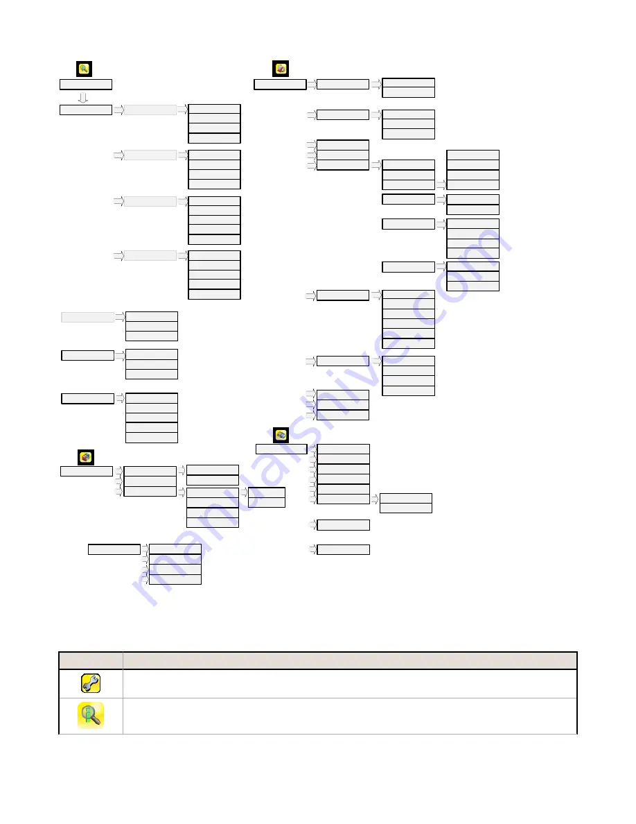
background image

Imager

Strobe

Auto Exposure

Exposure

Gain

Trigger

Focus

External

Internal

FOV

Resolution

* Visible when Motion = Enabled 

Add New

Startup

Delete

Stored Inspections

Sensors

Properties

Inspection ID

Motion **

Motion *

Number of Edges

Sensitivity

Rotation

Area

ROI and Mask

Intensity Range

Area Range

Pass Count

Blemish

ROI and Mask

Sensitivity

Edge Length Range

Pass Count

Match

ROI Type

Percent Match

Rotation Range

Pass Count

Sort

Saved Patterns

Percent Match

Rotation Range

Pass Criteria

Sensor Type selection determines 
first menu item under inspection

Inspection Name

Set Name / ID

Locked

Inspection Logs

System Logs

Communication Logs

Unlock Sensor

Logs

Inspection Logs

System Logs

Communication Logs

Command Channel

Data Export

Image Export

Locked Sensor Menus

Industrial Ethernet

Setup

View Logs

Setup

View Logs

   Live

   Demo

    Information

Mode

Save to USB

Load from USB

Reset to Defaults

Configuration

Lock Device

Serial I/O

Data Export

Image Export

Communications

Connection

Data to Export

Output Format

Input Polarity

Input Pullup

Output Type

Output 1

Discrete I/O

Command Channel

Connection

Connection

Delimiters

Fail Hold Time

LCD Timeout

Touch Calibration

Advanced

Display Settings

Output 2

Output 3

Reboot Sensor

Firmware Update

Language

Ethernet I/O

Advanced

Image Type

Advanced

Industrial Ethernet

Connection

Status

View Logs

** Visible when Inspection
contains Area or Blemish 

Inspection

Timeout

Map

Select

System

Timeout

Icon Reference

Action Icons

Icon

Description

The Main Menu icon is displayed on the bottom-left corner of the sensor display on the Home screen. It

provides access to sub-menus that are used to set up the sensor.

The Inspection menu icon is located on the the Main Menu, and provides access to parameters that need

to be set for the current and all stored inspections.

iVu Plus TG Gen2 Series Sensor


P/N 178442 Rev. B

www.bannerengineering.com - Tel: +1-763-544-3164

5

Summary of Contents for iVu Plus TG Gen2

Page 1: ...ed Display datasheet P N 179044 iVu Plus TG Gen2 with Remote Display datasheet P N 179045 iVu Plus TG Gen2 Instruction Manual P N 179042 iVu Plus Industrial Ethernet User s Guide P N B_3095133 In addi...

Page 2: ...l shown C Mount model connections are identical Power I O Connections Pin Wire Color Description Direction 1 White Output 1 Output 2 Brown 10 30V dc Input 3 Green Output 2 Output 4 Yellow Strobe Out 5...

Page 3: ...und Input 8 Red Ready Output 9 Orange Output 3 Output 10 Light Blue RS 232 TX Output 11 Black RS 232 Signal Ground Output 12 Violet RS 232 Rx Input Demo Mode The first time you power up the iVu Plus T...

Page 4: ...ck for the presence of some label or marking on a part that may vary in color Match Sensor A Match type sensor is used to verify that a pattern shape or part in any orientation matches a reference pat...

Page 5: ...to USB Load from USB Reset to Defaults Configuration Lock Device Serial I O Data Export Image Export Communications Connection Data to Export Output Format Input Polarity Input Pullup Output Type Outp...

Page 6: ...r icon is located on the lower right of the sensor display on the Home screen and is used to manually capture a new image The Save icon is used to save data to USB drive and is available at the bottom...

Page 7: ...ndicates that the command has been processed without errors Indicates that the incoming entry is stalled no new bytes or end of frame delimiter was not received or client is not reading data on ethern...

Page 8: ...sensor using the clear Focusing Window B 2 Adjust focus while monitoring the focus number To ensure the best image adjust the focus until the Focus Number peaks NOTE Turning the Focusing Window counte...

Page 9: ...ct it Use the dropdown list to selectExternal Trigger Internal Trigger default Free Run Industrial Ethernet Only or Command If Internal Trigger is selected triggers are based on timed intervals and yo...

Page 10: ...New 2 Select the Sensor Type for the new inspection and click Next 3 Click Done The newly created inspection will now be the current inspection Changing Running Inspections To change the running insp...

Page 11: ...access the channels go to Main Menu System Communications Command Channel a bi directional communication protocol that currently supports ASCII and enables other devices to remotely control the iVu Pl...

Page 12: ...N LIEU OF ALL OTHER WARRANTIES WHETHER EXPRESS OR IMPLIED INCLUDING WITHOUT LIMITATION ANY WARRANTY OF MERCHANTABILITY OR FITNESS FOR A PARTICULAR PURPOSE AND WHETHER ARISING UNDER COURSE OF PERFORMAN...

Reviews: