background image

EZ Build Assembly and Installation

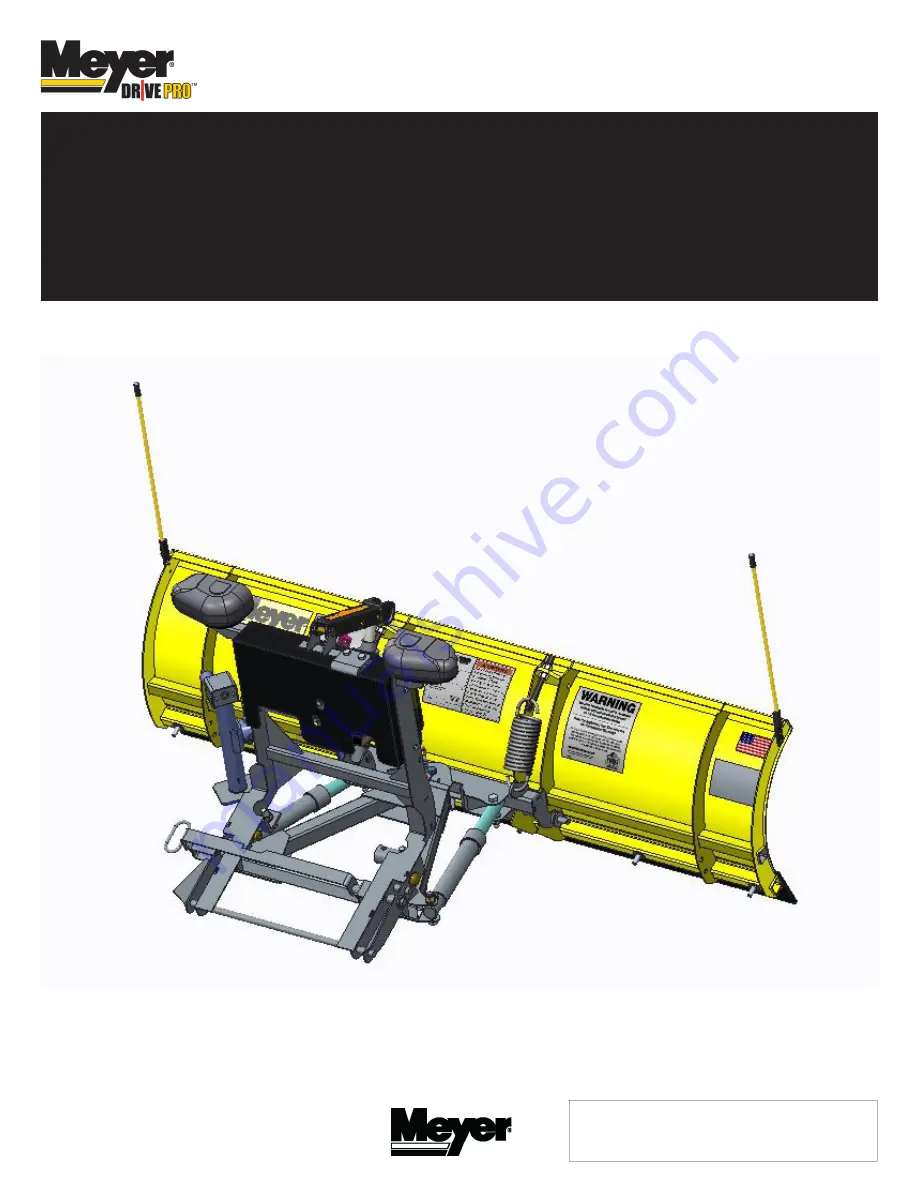
41130 Drive Pro 6.8 & 7.6 Plow Standard Operating System with E-73 12V Hydraulic Unit

and

41180 Drive Pro 6.8 & 7.6 Plow Standard Operating System with E-73 12V Hydraulic Unit

© 2016 Printed in the U.S.A.

Meyer Products LLC

18513 Euclid Ave. • Cleveland, Ohio 44112-1084

Phone 216-486-1313

www.meyerproducts.com• 

email [email protected]

Meyer  Products  LLC  reserves  the  right,  under  its  continuing  product 

improvement program, to change construction or design details, specifications 

and prices without notice or without incurring any obligation.

Form No. 1-1133R 

May 2016

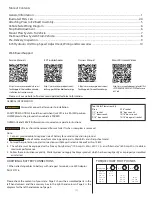
Summary of Contents for Drive Pro EZ Build 41130

Page 1: ...aulic Unit 2016 Printed in the U S A Meyer Products LLC 18513 Euclid Ave Cleveland Ohio 44112 1084 Phone 216 486 1313 www meyerproducts com email info meyerproducts com Meyer Products LLC reserves the right under its continuing product improvement program to change construction or design details specifications and prices without notice or without incurring any obligation Form No 1 1133R May 2016 ...

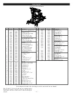
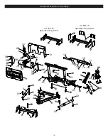
Page 2: ... Amp Min to obtain maximum performance 5 Follow these instructions explicitly Warranty does not apply to a Meyer product which has been negligently or improperly assembled or installed Please check the contents of your crate Page 2 shows the assembled parts in the left hand column and the accessory box in the right hand column Page 3 is the diagram for the left hand column of page 2 Bolt Nut Size ...

Page 3: ...ith Hose Fittings 2 05887 05887 1 Ram 1 1 2 x 10 3 22866 22866 1 SAE 6 x 90 Degree Elbow 4 22885 22885 1 Hose Assy 1 4 x 54 M 6 07783 07783 1 RH Ram with Hose Fittings 2 05887 05887 1 Ram 1 1 2 x 10 3 22866 22866 1 SAE 6 x 90 Degree Elbow 4 22921 22921 1 Hose Assy 1 4 x 38 M 6 5 10514 10514 1 Lift Arm 6 14250 14250 1 Pivot Bar Drive Pro 6 8 7 14185 14185 1 E 73 DP Mounting Bracket 8 14232 14232 1 ...

Page 4: ...fic Components 41180 E 73 Specific Components 3 1 2 5 6 7 8 9 10 2 11 12 13 16 17 18 19 20 12 14 15 14 17 18 20 21 22 23 24 25 26a 27 28 29 30 21 21 21 22 22 22 22 23 24 26 27 30 35 35 35 35 36 36 36 36 37 38 38 38 39 40 40 40 41 42 43 50 52 53 52 ...

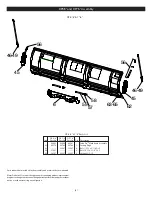
Page 5: ... x 3 1 4 Gr 5 65 20307 20307 20307 8 Locknut 1 2 13 DP 6 8 7 6 Parts List Parts indented are included in the assembly under which they are indented MeyerProductsLLCreservestheright underitscontinuingproductimprovement program tochangeconstructionordesigndetails specificationsandpriceswithout notice or without incurring any obligation DP 6 8 7 6 4 DP6 8 and DP7 6 Assembly 62 63 65 6 56 57 58 59 46 ...

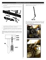
Page 6: ...f slack This ensures that the plow blade will lift fully and be able to follow the ground contour while plowing 5 C Attach Eye Bolts 56 to Moldboard and Trip Springs 45 to Pivot Bar 6 making certain locknuts are positioned as shown below D Make certain each Eye Bolt 56 is in a vertical position as shown below so that the Eye Bolt 56 andTrip Spring 45 hinge properly when moldboard trips Note Proper...

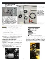
Page 7: ... on the Plow Side Harness 31 Check snow plow light blinkers to make sure the wires have not been reversed Note All electrical connections should have both ends coated with a dielectric grease Meyer Part No 15632 prior to final installation This will ensure a good connection and help in preventing corrosion K Refer to Operation and Maintenance Manual for complete controller operation Hydraulic Sole...

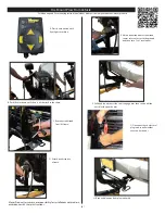
Page 8: ... the pins A Pull vehicle into plow assembly and push plow assembly forward an inch or two C Push back on lift frame until pins spring thru mount on vehicle For Mounting and Dis mounting instructional video s please visit www youtube com meyerproducts 7 Meyer Products assumes no responsibility for installations not made in accordance with these instructions G Remove weather cover on both ends and c...

Page 9: ... is a little slack in the chain C Remove crankstand from lift frame D Attach crankstand to a frame E Adjust crankstand until crankstand comes into contact with the ground and then turn 1 to 2 revolutions F Pull handle on drivers side to dis engage pins then twist until the notch locks open the pins H Back vehicle away from plow assembly 8 A Press down button until float light turns blue G Disconne...

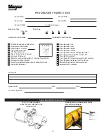
Page 10: ...ctric grease applied to ALL electrical connection All wires modules secured Plow Stops Adjusted plow cannot bump hyd unit Controller Operation Plow Operation Up Plow Operation Left Plow Operation Right Plow Operation Down Plow Light Blinker Left Right Operation Plow Light Low High Beam Operation Plow Lights Adjusted Plow Mount Dismount reviewed with Customer Plow Operation reviewed with Customer W...

Page 11: ...r a complete listing of accessories E 73 Wire and Hose Locations To Plow Lights To Vehicle Harness A Valve Black Black with White Stripe B Valve Red Black with White Stripe C Valve Green Black with White Stripe Left Angle Cylinder Right Angle Cylinder Lift Cylinder Motor Solenoid White Motor Solenoid Purple E 73 Drop Speed Adjustment Loosen jam nut and turn knob clockwise to slow the drop of the p...

Reviews: