Icon
Description
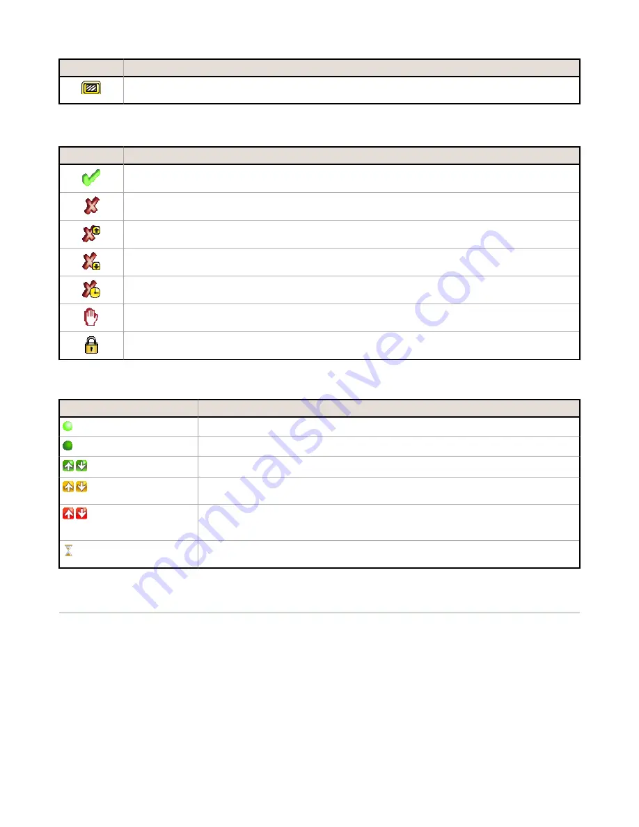
The Rectangular Mask icon displays on the left side of the screen when a mask is selected. Press to cycle
through and select a Circular, Elliptical, or Rectangular-shaped mask.
Display Icons
Icon
Description
The Inspection Passed icon is located in the upper-left of the screen, and indicates that the last inspection
passed its test conditions.
One of the possible Inspection Failed icons located in the upper-left of the screen, it indicates that the last
inspection failed.
One of the possible Sensor Failed icons located in the Inspection Statistic table, it indicates that the
sensor failed because the number of objects exceeded the test count.
One of the possible Sensor Failed icons located in the Inspection Statistic table, it indicates that the
sensor failed because there were fewer objects than specified by the test count.
One of the possible Sensor Failed icons located in the Inspection Statistic table, it indicates that the
sensor failed because the inspection timed out.
One of the possible Inspection Failed icons located in the upper-left of the screen, it indicates that the
sensor is in fail hold mode.
The Sensor Locked icon is located in the upper-left of the screen, and indicates that the sensor is in a
locked state. If no icon is displayed, the sensor is unlocked.
Communications Log Icons
Icon
Description
Port opened.
Port closed.
Indicates that the command has been processed without errors.
Indicates that the incoming entry is stalled (no new bytes), or end-of-frame delimiter
was not received, or client is not reading data on ethernet.
If the response frame contains an error or is dropped, the log entry icons for the request
and the response frames will be colored red, and the displayed error count will
increment by one.
If the command takes a long time to process, the last long entry will change to an
hourglass (for example, during trigger of long inspections).
Acquiring a Good Image
The iVu Series sensor needs to capture a good image of each part to ensure that it correctly passes good parts and fails
bad parts.
1. Go to Main Menu > Imager > Auto Exposure to run the Auto Exposure routine.
2. Check the lighting.
•
Make sure that the lighting is constant and consistent (unchanging over time, no shadows or hot spots).
•
Capture the shape and form of the target object with lighting that optimizes its contrast and separates it
from the background. Depending on the target, this may mean the integral ring light is not the best choice
and other Banner lights should be considered.
•
Adjust the mounting angle to provide the clearest image of the part features you are monitoring. The
mounting bracket lets you easily position and adjust the sensor on your line.
3. If needed, go to Main Menu > Imager > Auto Exposure to run the Auto Exposure routine a second time or
adjust Gain and Exposure manually:
•
Main Menu > Imager > Gain
iVu Plus TG Gen2 Series Sensor
P/N 178442 Rev. B
www.bannerengineering.com - Tel: +1-763-544-3164
7


