Choose from the following components to make up the backbone:
•
Micro-C cables: 0.6 m (2 ft), 1.8 m (6 ft), 4.5 m (15 ft), and 7.6 m (25
ft) cables.
•
T-connector or 4-way connector. Used to connect a drop cable
to the backbone.
•
Micro-C power cable. Connect to the backbone at a position that
is central to the network load using a T-connector or 4-way
connector.
Ú
Note:
When using a wind sensor, the mast cable should be
connected at one end of the backbone, as the sensor is
fitted with a termination resistor.
Ú
Note:
Most NMEA 2000 devices can be connected directly
to a SimNet backbone and SimNet devices can be
connected to a NMEA 2000 network by using adapter
cables.
Power the network
The network requires its own 12 V DC power supply protected by a
3 amp fuse or breaker.
Connect power at any location in the backbone for smaller systems.
For larger systems introduce power at central point in the backbone
to “balance” the voltage drop of the network.
Ú
Note:
If joining to an existing NMEA 2000 network that
already has its own power supply, do not make another
power connection elsewhere in the network, and ensure
the existing network is not powered by 24 V DC.
Ú
Note:
Do not connect the NMEA 2000 power cable to the
same terminals as the engine start batteries, autopilot
computer, bow thruster or other high current devices.
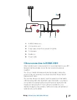
The following drawing demonstrates a typical small network. The
backbone is made up of directly interconnected T-connectors.
26
Wiring
| Vulcan Series Installation Manual
Summary of Contents for Vulcan Series
Page 1: ...ENGLISH VulcanSeries Installation Manual bandg com...
Page 2: ......
Page 8: ...8 Preface Vulcan Series Installation Manual...
Page 64: ...988 11099 001 0980...

