

7 / 26
0006081362_20
1403
N° 0002910950n1
ENGLISH
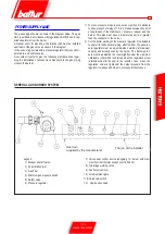
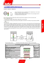
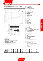
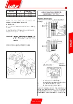
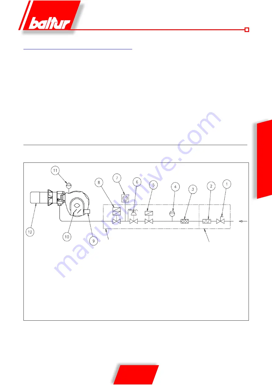
Legend
1) Manual shut off valve
2) Anti-vibration joint
3) Gas filter
4) Minimum gas pressure switch
5) Safety valve
6) Pressure regulator
Gas train
supplied by the manufacturer
The job of the installer
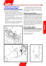
POWER SUPPLY LINE
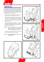
The gas supply scheme is shown in the diagram below. The gas
train is certified in accordance with regulations EN 676 and is sup-
plied separately from the burner.
A manual shut off valve and anti-vibration joint must be installed
upstream of the gas valve, as shown in the diagram.
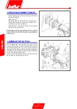
In the case of a gas train with a pressure regulator that is not incor-
porated in a monoblock valve,
we consider it useful to give the following practical advice regar-
ding the installation of accessory components to the gas piping
close to the burner:
1) To prevent severe drops in pres-sure on ignition it is advisble
to have a length of piping of 1.5 to 2 metres between the point
of application of the stabiliser or pressure reducer and the
burner. This pipe must have a diameter equal to or greater
than the connector to the burner.
2) For the better working of the pressure regulator it is advisable
to apply it to the horizontal piping, after the filter. The gas pres-
sure regulator must be adjusted when working at maximum
capacity and actually used by the burner. The delivery pres-
sure must be adjusted to a level slightly below the maximum
obtainable. (that which is obtained when the regulation screw
is turned almost to the end); in the specific case, when the
regulation screw is tightened, the output pressure from the
regulator increases and when it is loosened it decreases.
GENERAL GAS BURNER SYSTEM
7) Valves seal control device (obligatory for burner with maxi-
mum nominal thermal out-put over 1200 kW)
8) Two-stage working valve
9) Control servomotor
10) Air adjustment gate
11) Air pressure switch
12) Combustion head
Summary of Contents for TBG 45
Page 2: ......
Page 24: ...22 26 0006081362_201403 ENGLISH ...
Page 25: ...23 26 0006081362_201403 ENGLISH ...
Page 26: ...24 26 0006081362_201403 ...
Page 27: ...25 26 0006081362_201403 ...
Page 50: ...22 26 0006081362_201403 ESPAÑOL ESQUEMA ELECTRICO ...
Page 51: ...23 26 0006081362_201403 ESPAÑOL ...
Page 52: ...24 26 0006081362_201403 ...
Page 53: ...25 26 0006081362_201403 ...
Page 76: ...22 26 0006081362_201403 FRANÇAIS SCHEMA ELECTRIQUE ...
Page 77: ...23 26 0006081362_201403 FRANÇAIS ...
Page 78: ...24 26 0006081362_201403 ...
Page 79: ...25 26 0006081362_201403 ...
Page 102: ...22 26 0006081362_201403 TÜRKÇE ELEKTRİK ŞEMASI ...
Page 103: ...23 26 0006081362_201403 TÜRKÇE ...
Page 104: ...24 26 0006081362_201403 ...
Page 105: ...25 26 0006081362_201403 ...
Page 130: ...24 26 0006081362_201403 ...
Page 131: ...25 26 0006081362_201403 ...
Page 154: ...22 26 0006081362_201403 中 文 电气图 ...
Page 155: ...23 26 0006081362_201403 中 文 ...
Page 156: ...24 26 0006081362_201403 ...
Page 157: ...25 26 0006081362_201403 ...
Page 159: ......