15 / 26
0006081362_20
1403
ENGLISH
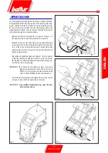
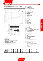
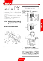
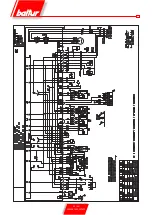
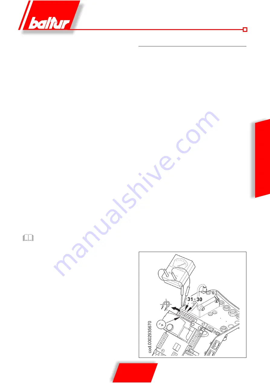
IONISATION CURRENT MEASUREMENT
To measure the ionisation current, remove the jumper
between terminals 30-31 on the printed circuit with the
burner off (see diagram). Connect a microampmeter to the
terminals (with a suitable scale to have the burner restart).
Once the flame has appeared it will be possible to measure
the ionisation current, the minimum value of which to ensure
the working of the equipment is shown in the specific wiring
diagram. After making the measurement, reset the jumper
that has been disconnected.
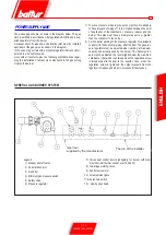
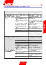
when the fan is stopped (no air pressure in burner). If it is not the
command and control equipment will not go on (the burner stays
stopped). If the air pressure switch does not detect pressure
greater than that calibrated, the equipment runs through its
cycle but does not switch on the ignition transformer and does
not open the gas valves and so the burner “locks-out”. To
ensure correct working of the air pressure switch you must,
with burner on and with first flame only, increase the regulation
until it is triggered and immediately “locks-out” the burner.
To release the burner, press the release button and adjust the
pressure switch to a sufficient level to detect the existing air
pressure during the preventilation stage.
•
The control pressure switches for the gas (minimum) are to
prevent the working of the burner when the pressure of the gas
is not as provided for. It is clear from the specific function of the
pressure switches that the control pressure switch for minimum
pressure must make use of the contact that is closed when the
pressure switch detects a pressure greater than that for which
it is regulated. The adjustment of the minimum gas pressure
switch must therefore be carried out when the burner is started
up, in accordance with the pressure that is found at the time. The
triggering (i.e. the opening of the circuit) of any of the pressure
switches when the burner is running (flame on) cause the burner
to stop immediately. On first switching on of the burner it is
essential to check the correct working of the pressure switch.
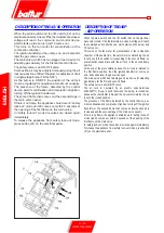
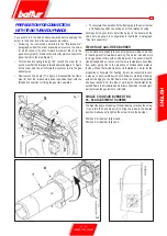
•
Check the triggering of the flame detector (ionisation electrode)
by disconnecting the jumper between terminals 30 and 31 on the
printed circuit board and switching on the burner. The equipment
must run through its cycle completely and, three seconds after
the ignition flame has formed, “lock-out”. This check must
also be carried out the burner already on. Disconnecting the
30 and 31 jumper, the equipment must immediately go into its
“lock-out” action.
•
Check the proper working of the boiler thermostats or pressure
switches (when triggered they must stop the burner).
Check that the switch on occurs normally since if the
adjuster is shifted forward, it may happen that the speed
of the delivery air is so high that ignition is difficult. If this
happens, the adjust must be shifted back by degrees until it
is in a position in which ignition occurs normally, and this new
position can be regarded as the final position. We remind you
that is preferable, in the case of the small flame, to limit the
quantity of air to the least possible needed for safe ignition,
even in the most difficult circumstances.
Summary of Contents for TBG 45
Page 2: ......
Page 24: ...22 26 0006081362_201403 ENGLISH ...
Page 25: ...23 26 0006081362_201403 ENGLISH ...
Page 26: ...24 26 0006081362_201403 ...
Page 27: ...25 26 0006081362_201403 ...
Page 50: ...22 26 0006081362_201403 ESPAÑOL ESQUEMA ELECTRICO ...
Page 51: ...23 26 0006081362_201403 ESPAÑOL ...
Page 52: ...24 26 0006081362_201403 ...
Page 53: ...25 26 0006081362_201403 ...
Page 76: ...22 26 0006081362_201403 FRANÇAIS SCHEMA ELECTRIQUE ...
Page 77: ...23 26 0006081362_201403 FRANÇAIS ...
Page 78: ...24 26 0006081362_201403 ...
Page 79: ...25 26 0006081362_201403 ...
Page 102: ...22 26 0006081362_201403 TÜRKÇE ELEKTRİK ŞEMASI ...
Page 103: ...23 26 0006081362_201403 TÜRKÇE ...
Page 104: ...24 26 0006081362_201403 ...
Page 105: ...25 26 0006081362_201403 ...
Page 130: ...24 26 0006081362_201403 ...
Page 131: ...25 26 0006081362_201403 ...
Page 154: ...22 26 0006081362_201403 中 文 电气图 ...
Page 155: ...23 26 0006081362_201403 中 文 ...
Page 156: ...24 26 0006081362_201403 ...
Page 157: ...25 26 0006081362_201403 ...
Page 159: ......