

14 / 26
0006081362_20
1403
ENGLISH
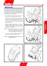
METHANE GAS IGNITION
AND ADJUSTMENT
•
Check that there is water in the boiler and that the gate valves
for the system are open.
•
Check, with complete certainty, that the discharge of combustion
products can take place freely (boiler and flue gates open).
•
Check that the voltage of the electrical line corresponds to
the burner voltage. Electrical connections (motor and main
line) must be prepared for the voltage available. Check that all
electrical connections made on-site are performed correctly as
shown in our wiring diagram. Prevent the second flame from
functioning by disconnecting the 4 pole connector (18) from
the electrical panel (0002935620) for TBG 45P-60P burners;
for TBG 45 60 burners, disconnect the wire from terminal 5
on the terminal board on the printed circuit supplying coil Y2.
•
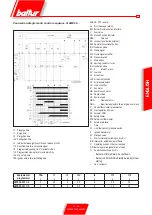
Adjust air for the ignition flame :
- for TBG 45P - 60P burners with an electric servomotor, follow
the instructions given in card 0002934711;
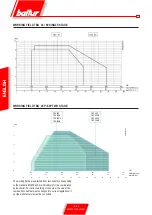
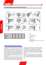
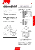
- for burner TBG 45 - 60 with manual adjustment, adjust the
air for the second flame on the basis of the instructions given
in the section entitled “Diagram for adjustment of air in TBG
45-60 single-stage burner”.
•
Carefully manoeuvre the gas adjustment device valve to open,
for the amount presumed necessary, the first flame flow adjuster
(see the instructions for the two-stage gas valve for the model
installed on the burner). If necessary, of course, open the safety
valve flow adjuster completely if there is one.
•
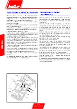
For three phases burners, with the switch I/O (22) on the burner
panel (see 000293560) at the position “0” and the main switch
on, check, closing the contactor manually, that the motor rotates
in the right direction, if necessary swap the two power cables for
the motor around to change the direction of rotation.
•
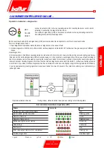
Now switch on the control panel switch (22). The control
equipment thus receives voltage and the programmer
causes the burner to switch on as described in the chapter
“description of working”. During the preventilation stage you
must check that the air pressure control switch carried out the
exchange (from the closed position without pressure detection
it must go to the closed position detecting air pressure).
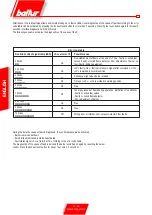
If the air pressure switch does not detect sufficient pressure
(does not carry out the exchange) the ignition transformer is
not switched on, nor are the gas valves, and so the equipment
is stopped in its “lock-out” mode. On first switching on repeated
“lock outs” may occur due to:
- the gas piping not being freed of the air sufficiently and so the
gas quantity is not enough to provide a stable flame.
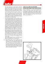
- “lock out” with flame present maybe caused by instability in
the ionisation area, due to an incorrect air/gas ratio. This can
be remedied by varying the quantity of air and/or gas until
the right ratio is found. The same problem may be caused
by incorrect air/gas distribution in the combustion head.
This can be remedied with the combustion head adjustment
device by closing or opening further the air passage between
combustion head and gas diffusor.
- It may happen that the ionisation current is interfered with
by the discharge current of the ignition transformer (the
two currents have a common path on the burner’s “mass”)
so the burner gets locked out due to insufficient ionisation.
This can be remedied by inverting the supply (230V side)
of the ignition transformer (swapping the two wires carrying
voltage to the transformer). This problem may also be caused
by an insufficient “ground connection” from the burner’s
casing.
•
With the burner on at minimum you must carry out an immediate
visual check on the extent of and appearance of the flame,
performing the necessary corrections with the gas and air supply
regulators (see points 4 and 5). Subsequently a check is carried
out on the quantity of gas supplied, by reading the meter. If
necessary the gas supply and the corresponding combustion
air can be corrected as previously described (points 4 and
5). Subsequently the combustion is checked with the special
instruments. For a correct air/gas ratio you must find a carbon
dioxide (CO
2
) value for the methane that is at least 8 % or O
2
= 6% at minimum burner supply up to an optimal value of 10
% or O
2
= 3% for maximum supply. It is essential to check, with
a suitable instrument, that the percentage of carbon monoxide
(CO) present in the fumes does not exceed the limit set by
regulations at the time of installation.”
•
Repeatedly check that the first flame is supplied correctly.
After adjusting operation with the first flame, turn off the
burner, open the main switch and close the electrical
circuit commanding inclusion of the second flame:
reinsert the 4 pole connector previously disconnected in
the case of TBG 45P-60P burners; reconnect the wire
to terminal 5 on the terminal board on the printed circuit
supplying coil Y2 in the case of TBG 45-60 burners.
Open the manual regulator for the gas supply for the second
flame (main flame) to the presumed necessary quantity.
Now switch the burner on again, closing the master switch
and that on the control panel. The burner switches on and
automatically switches on the second flame (main flame). Carry
out an immediate visual check on the extent of and appearance
of the flame, performing the necessary corrections with the gas
and air supply regulators as indicated in points 4 and 5.
•
Use the adjuster to set the correct flow for the second flame as
required for the specific case. You must not keep the burner
running if the capacity is greater than the maximum permitted
amount for the boiler, or there is a risk it could be damaged.
It is therefore best to stop the burner immediately after the
twometer readings.
•
Subsequently, with the burner at maximum supply required by
the boiler, check the combustion with the special instruments
and if necessary change the adjustment previously carried out
(air and possibly gas) with just the visual check (CO
2
max. =
10 % O
2
min =3% - CO max. = 0.1%
•
The air pressure switch is there to prevent the opening of the
gas valves if the air pressure is not that required. The pressure
switch must therefore be adjusted to intervene to close its
contact when the air pressure in the burner reaches a sufficient
value. The pressure switch connection circuit provides for auto
control so it necessary for the contact to be actually closed
Summary of Contents for TBG 45
Page 2: ......
Page 24: ...22 26 0006081362_201403 ENGLISH ...
Page 25: ...23 26 0006081362_201403 ENGLISH ...
Page 26: ...24 26 0006081362_201403 ...
Page 27: ...25 26 0006081362_201403 ...
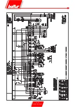
Page 50: ...22 26 0006081362_201403 ESPAÑOL ESQUEMA ELECTRICO ...
Page 51: ...23 26 0006081362_201403 ESPAÑOL ...
Page 52: ...24 26 0006081362_201403 ...
Page 53: ...25 26 0006081362_201403 ...
Page 76: ...22 26 0006081362_201403 FRANÇAIS SCHEMA ELECTRIQUE ...
Page 77: ...23 26 0006081362_201403 FRANÇAIS ...
Page 78: ...24 26 0006081362_201403 ...
Page 79: ...25 26 0006081362_201403 ...
Page 102: ...22 26 0006081362_201403 TÜRKÇE ELEKTRİK ŞEMASI ...
Page 103: ...23 26 0006081362_201403 TÜRKÇE ...
Page 104: ...24 26 0006081362_201403 ...
Page 105: ...25 26 0006081362_201403 ...
Page 130: ...24 26 0006081362_201403 ...
Page 131: ...25 26 0006081362_201403 ...
Page 154: ...22 26 0006081362_201403 中 文 电气图 ...
Page 155: ...23 26 0006081362_201403 中 文 ...
Page 156: ...24 26 0006081362_201403 ...
Page 157: ...25 26 0006081362_201403 ...
Page 159: ......