


1-800-543-8390
•
WWW.BALLUFF.COM
6
BTL5-A/C/E/G__-M____-B/Z-S32/KA__
Micropulse Linear Position Transducer
Analog Output-Rod Style
™
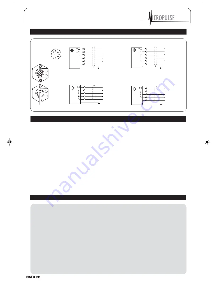
4 Wiring (cont.)
5 Startup
5.1 Check connections
Although the connections are
polarity reversal protected,
components can be damaged by
improper connections and
overvoltage. Before you apply
power, check the connections
carefully.
5.2 Turning on the system
Note that the system may
execute uncontrolled movements
when first turned on or when the
transducer is part of a closed-
loop system whose parameters
have not yet been set.
Therefore make sure that no
hazards could result from these
situations.
5.3 Check output values
After replacing or repairing a
transducer, it is advisable to verify
the values for the start and end
position of the magnet in manual
mode. If values other* than those
present before the replacement or
repair are found, a correction should
be made.
* Transducers are subject to
modification or manufacturing
tolerances.
5.4 Check functionality
The functionality of the
transducer system and all its
associated components should
be regularly checked and
recorded.
5.5 Fault conditions
When there is evidence that
the transducer system is not
operating properly, it should be
taken out of service and
guarded against unauthorized
use.
Please note:
The calibration device is to be
attached to the connection end
of the transducer as shown in
Fig. 6-1. Connect the trans-
ducer to the controller. To moni-
tor the calibration procedure, a
display (controller or multimeter)
which displays the BTL voltage
or current levels is required.All
settings are done with a mag-
net within the stroke area.
Please verify that the absolute
null- and endpoints are always
within the maximum and
minimum possible output values
(value table 7-1 on page 8).
6 Calibration procedure
2
GY
3
PK
5
GN
7
BN
6
BU
8
WH
Analog common
Analog output, falling
Analog output, rising
Analog Voltage
24 V (A, B, G)
+24 V
GND
GND
0117a021
1
2
3
4
5
6
7
8
View of mating
connector, wiring side
2
GY
1
YE
7
BN
6
BU
8
WH
Analog common
Analog output
Analog Current
24 V (E, C)
+24 V
GND
GND
0117a023
2
GY
3
PK
5
GN
7
BN
6
BU
8
WH
Analog common
Analog output, falling
Analog output, rising
Analog Voltage
±15 V (A, B, G)
+15 V
GND
-15 V
0117a022
2
GY
1
YE
7
BN
6
BU
8
WH
Analog common
Analog output
Analog Current
±15 V (E, C)
+ 15 V
GND
-15 V
0117a024
Connector
Cable out
Any desired magnet position within
the factory set nominal stroke length
can be assigned with a null- or
endpoint. Do not however reverse the
null- and endpoints.
Once the calibration procedure is
concluded, the calibration device
can be removed to prevent accidental
changes and to store in a safe place
for the next use.
The examples shown in this handbook
refer to the two versions with 0 to 10
V and 4 to 20 mA outputs. For all
other versions the corresponding
values can be found in the value table
7-1 on page 8.
The buttons are automatically
disabled after approximately
10 minutes of non-use.
Advantages:
The display will always indicate
the current position value even
during the calibration procedure.
The last programmed values
remain stored, regardless of
whether the programming mode
is ended manually by pressing
the buttons or automatically
after 10 minutes.
Z_Analog_122003.pmd
12/11/2003, 3:47 PM
6