


1-800-543-8390
•
WWW.BALLUFF.COM
4
BTL5-A/C/E/G__-M____-B/Z-S32/KA__
Micropulse Linear Position Transducer
Analog Output-Rod Style
™
0.5
74
12
~ 27
~ 27
~ 53
11
Ø 6.5
25
60 ±0.5
Ø 10.2
45
SW 46
1 2
3 Installation (cont.)
Nominal length
= measuring range
Damping zone (unusable area)
Mounting
surface
Electrical connection
Magnet
Thread size: B: M18×1.5 (includes nut)
Z: 3/4"-16UNF
B: 30 mm
Z: 2"
Blind hole
M4 × 4/6 deep
Magnet
BTL5...B/Z-KA05
BTL5...B/Z-S 32
Calibration
device
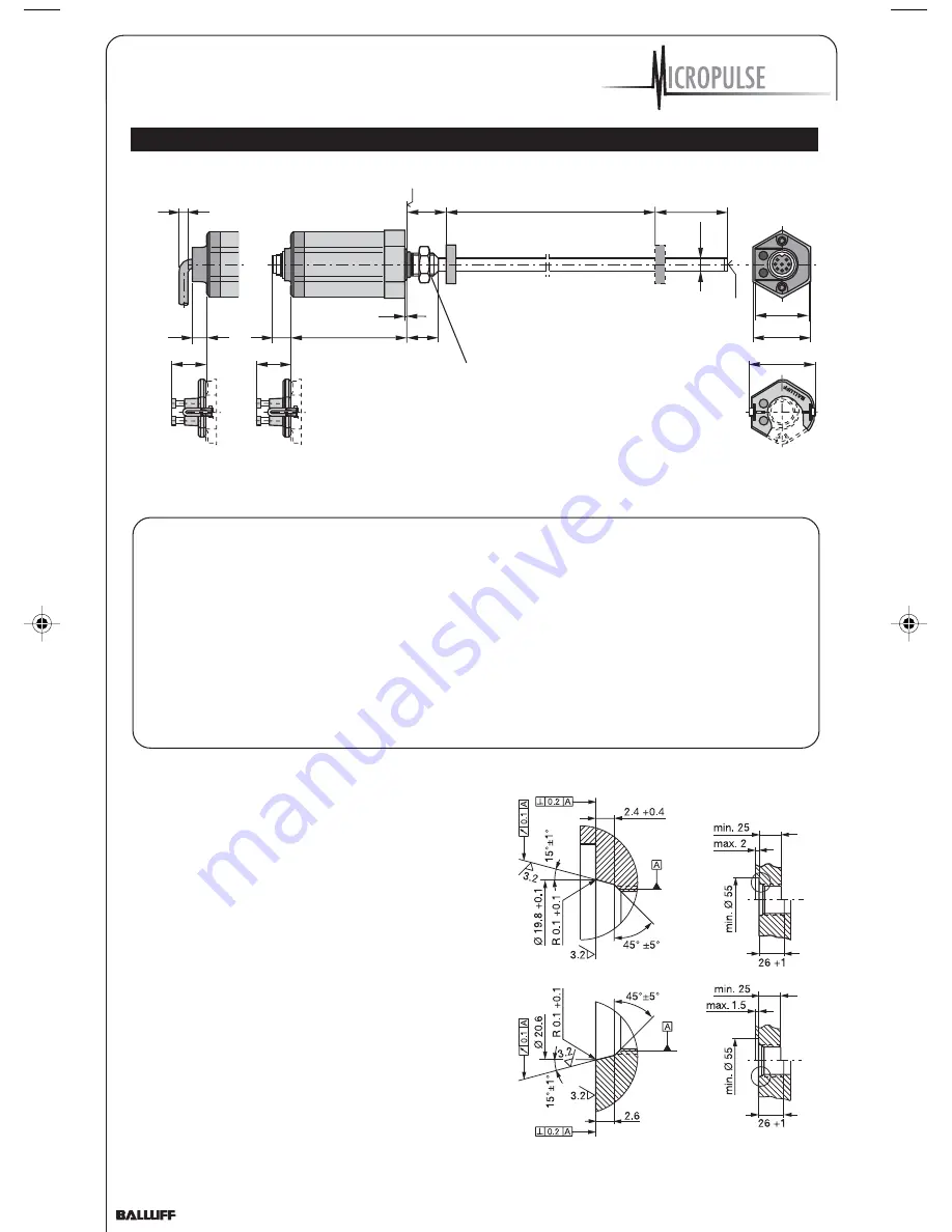
Fig. 3-2: Transducer BTL5...B/Z, Dimensions
Important Installation Notes:
The contact surface of the
transducer must be
completely contacted by the
mounting surface. The O-ring
supplied must make a perfect
pressure seal, i.e. the bevel
for the O-ring must be
configured exactly as shown
in Fig. 3-3.
To achieve secure mounting,
use the proper nut for the
mounting thread. When
tightening the nut, do not exceed a
tightening torque of 100 Nm.
For horizontal mounting of
transducer with stroke lengths
greater than 500 mm, the pressure
tube should be supported or
attached at its end.
When installing in a hydraulic
cylinder, do not allow the magnet
ring to rub against the pressure
tube. The bore diameter in the
piston and cylinder
rod should be at least 13 mm.
When attaching the transducer
to magnetizable materials,
appropriate measures must be
taken to protect against
magnetic disturbances,
Fig. 3-1.
Note the recommended
distance of the transducer and
cylinder from strong, external
magnetic fields.
3.2 Transducer, Installation
The smallest permissible distance
between magnet ring and rod mounting
surface is shown in Fig. 3-2.
The transducer has either a M18×1.5
thread or a 3/4"-16UNF thread for
mounting. The sealing is carried out
with the O-ring supplied at the
flange facing.
Fig. 3-3: Threaded hole for mounting the BTL with O-ring
Threaded hole
M18×1.5 per
ISO 6149
O-ring 15.4 × 2.1
Threaded hole
3/4"-16UNF per
SAE J475
O-ring 15.3 × 2.4
Z_Analog_122003.pmd
12/11/2003, 3:47 PM
4