background image

www.balluff.com

2

No. 937341 EN · L17; Subject to modification. 

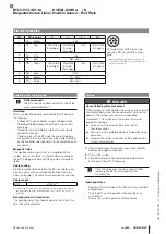
Startup

  DANGER

Uncontrolled system movement

When starting up, if the position measuring system is part 
of a closed loop system whose parameters have not yet 
been set, the system may perform uncontrolled 
movements. This could result in personal injury and 
equipment damage.


Persons must keep away from the system’s 
hazardous zones.


Startup must be performed only by trained technical 
personnel.


Observe the safety instructions of the equipment or 
system manufacturer.

1. 

Check connections for tightness and correct polarity. 

Replace damaged connections.

2. 

Turn on the system.

3. 

Check measured values and adjustable parameters 

and readjust the BTL if necessary.

Check for the correct values, especially after 

replacing the BTL or after repair by the 

manufacturer.

Operating Notes

–  Regularly check function of the BTL and all associated 

components.

–  Take the BTL out of operation whenever there is a 

malfunction.

–  Secure the system against unauthorized use.

Shielding and cable routing

Defined ground!

The BTL and the control cabinet must be at the 

same ground potential.

Shielding

To ensure electromagnetic compatibility (EMC), observe 

the following:
–  Connect BTL and controller using a shielded cable. 

Shielding: Braided copper shield with minimum 85% 

coverage.

–  Connector version: Shield is internally connected to 

connector housing.

–  Cable version: On the BTL side the cable shielding is 

connected to the housing. Ground the cable shielding 

on the controller side (connect with the protective earth 

conductor).

Magnetic fields

The position measuring system is a magnetostrictive 

system. Ensure that there is sufficient distance between 

the BTL, holding cylinder and strong, external magnetic 

fields.

Cable routing

Do not route the cable between the BTL, controller, and 

power supply near high voltage cables (inductive stray 

noise is possible). The cable must be routed tension-free.

Cable length

BTL5-…

≤ 500 m

4)

4) Prerequisite: Construction, shielding and routing preclude the effect of 

any external noise fields. Required cable cross-section ≥ 0.6 mm

2

 or 

≤ AWG19.

Bending radius for fixed cable

The bending radius for a fixed cable must be at least five 

times the cable diameter.

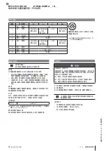
BTL5-P/I/L/M1-M _ _ _ _ -H/W(8) -S32/KA _ _ /K _ _

Magnetostrictive Linear Position Sensor – Rod Style

english

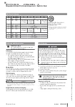
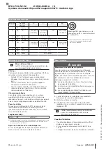
Electrical connection

Pin

Wire color

-P…

-I…

-L…

-M…


1

YE

Yellow

+Init

2

GY

Gray

+Start/Stop 

(2nd edge)

+Start/Stop  

(tri-state, 

2nd edge)

+Tor

+Start/Stop 

(1st edge)

Pin assignment of S32 (view from 

above on BTL), 8-pin M16 circular 

plug

3

PK

Pink

−Init

4

RD

Red

Not used

3)

3)  Unassigned leads that are not used can be 

connected to the GND on the controller side 
but not to the shield.

5

GN

Green

−Start/Stop 

(2nd edge)

−Start/Stop  

(tri-state, 

2nd edge)

−Tor

−Start/Stop 

(1st edge)

6

BU

Blue

GND

7

BN

Brown

20…28 V

8

WH

White

Not used

3)

Summary of Contents for BTL5-P/I/L/M1-M-H/W(8)-S32/KA/K Series

Page 1: ...deutsch Kurzanleitung english Condensed guide fran ais Notice r sum e italiano Istruzioni brevi espa ol Instrucciones breves BTL5 P I L M1 M_ _ _ _ H W 8 S32 KA_ _ K_ _...

Page 2: ...ser Positionsgeber ist mit dem Anlagen bauteil verbunden dessen Position bestimmt werden soll Der Positionsgeber definiert die zu messende Position auf dem Wellenleiter Einbau ACHTUNG Funktionsbeeintr...

Page 3: ...lecht aus Kupfer Einzeldr h ten Bedeckung mindestens 85 Steckerausf hrung Schirm im Steckverbinder mit dem Steckergeh use fl chig verbinden Kabelausf hrung BTL seitig ist der Kabelschirm mit dem Geh u...

Page 4: ...o the system part whose position is to be determined The magnet defines the position to be measured on the waveguide Installation NOTICE Interference in function Improper installation can compromise t...

Page 5: ...Connector version Shield is internally connected to connector housing Cable version On the BTL side the cable shielding is connected to the housing Ground the cable shielding on the controller side co...

Page 6: ...du guide d ondes Le capteur de position est reli l l ment de l installation dont la position doit tre d termin e Le capteur de position d finit la position mesurer sur le guide d ondes Montage ATTENT...

Page 7: ...avec un c ble blind Blindage tresse de fils de cuivre couverture minimum 85 Version connecteur relier plat le blindage du connecteur au bo tier de connecteur Version c ble c t BTL le blindage de c bl...

Page 8: ...quale deve essere determinata la posizione Il datore di posizione definisce la posizione da misurare sulla guida d onda Montaggio ATTENZIONE Anomalie funzionali Il montaggio non corretto pu ostacolare...

Page 9: ...mato Schermatura maglia di singoli fili di rame copertura minima 85 Versione con connettore collegare la schermatura nel connettore con il corpo del connettore sull intera superficie Versione con cavo...

Page 10: ...unido con el componente de la instalaci n cuya posici n se desea determinar El sensor de posici n define la posici n que se ha de medir en el gu aondas Montaje ATENCI N Merma del funcionamiento Un mon...

Page 11: ...alla de hilos individuales de cobre cobertura m nima del 85 Ejecuci n de conector conecte superficialmente el blindaje en el conector con la carcasa del mismo Ejecuci n de cable en el lado del BTL el...

Page 12: ...500 mm 10 2 mm 10 2 mm 13 mm 8 mm 11 mm BTL5 P I L M1 M_ _ _ _ H W 8 S32 KA_ _ K_ _ CE EMV UL E227256 65 21 35 42 0 5 25 20 20 10 43 25 12 60 D1 G 10 0 5 25 H M18 1 5 W 3 4 16UNF H 40 1mm W 2 0 04 1 B...

Page 13: ...85 BTL BTL BTL BTL5 500 m4 4 0 6 mm2 AWG19 BTL5 P I L M1 M_ _ _ _ H W 8 S32 KA_ _ K_ _ P I L M 1 YE Init 2 GY Start Stop 2 Start Stop 2 Tor Start Stop 1 S32 BTL 8 M16 3 PK Init 4 RD 3 3 GND 5 GN Start...

Page 14: ......

Page 15: ......

Page 16: ...uhausen a d F Phone 49 7158 173 370 Fax 49 7158 173 691 service balluff de US Service Center USA Balluff Inc 8125 Holton Drive Florence KY 41042 Phone 859 727 2200 Toll free 1 800 543 8390 Fax 859 727...

Reviews: