background image

www.balluff.com

2

english

BTL  PA0400- _ _ _ _ -B15A_010-000S92

Magnetostrictive Linear Position Sensor – Profile Style

953327_AA ∙ EN ∙ E22; subject to modification. Replaces K21.

Installation

NOTICE

Improper installation

Improper installation can compromise the function of the 
BTL and result in damage.


Ensure that no strong electrical or magnetic fields 
are present in the direct vicinity of the BTL.


Be sure to maintain the specified distances and 
separations.

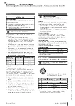
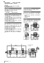
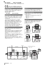
For dimensions, see figure.

Observe the following when installing the magnet:
–  To ensure the accuracy of the magnetostrictive linear 

position sensor, fasten the magnet to the moving 

member of the machine only using non-magnetizable 

screws (stainless steel, brass, aluminum).

–  The moving member must guide the magnet on a 

parallel line to the BTL.

–  Distance A between the magnet and parts made of 

magnetizable material must be kept to at least 10 mm 

(see figure).

For distance B between the magnet and the BTL and for 

the center offset C (see figure) the following values must be 

maintained:

Magnet type

Distance B

1)

Offset C

BTL6-A-3800-2

4…8 mm

2)

± 5 mm

BTL6-A-3801-2

4…8 mm

2)

± 5 mm

1) The selected distance must remain constant over the entire stroke 

length.

2) For optimal measurement results: 6…8 mm

The BTL is installed on a flat surface of the machine using 

mounting clamps or cuffs (available accessories). Any 

orientation is permitted. Note the recommended spacing 

for the location of clamps or cuffs (see figure).

1. 

Slide BTL into the mounting clamps or cuffs.

2. 

Align BTL slot in the direction of the magnet(s)!

3. 

Attach the BTL to the base (tighten screws in clamps 

or cuffs to max. 4 Nm tightening torque).

4. 

Installing magnet (accessory).

5. 

Check orientation of the BTL. If the groove does not 

point in the direction of the magnet, loosen the 

mounting screws and repeat steps 2 to 3.

Shielding and cable routing

Defined ground!

The BTL and the control cabinet must be at the 

same ground potential.

Shielding

Observe the following instructions to ensure 

electromagnetic compatibility (EMC):
–  Connect BTL and controller using a shielded cable.  

Shielding: Braided copper shield with minimum 85% 

coverage.


– Shield is internally connected to connector housing.

Magnetic fields

The position measuring system is a magnetostrictive 

system. Ensure that there is sufficient distance between 

the BTL and the transducer/holding cylinder and strong, 

external magnetic fields.

Cable routing

Do not route the cable between the BTL, controller, and 

power supply near high voltage cables (inductive stray 

noise is possible).

The cable must be routed tension-free.

Cable length

BTL …-B15AA/A1…

Max. 30 m

1)

BTL …-B15AE/A5…

Max. 100 m

1)

1) Prerequisite: Construction, shielding and routing preclude the effect of 

any external noise fields.

Electrical Connection

The electrical connection is made via a plug connection.

See the information about 

Shielding and cable 

routing

.

3

1

4

2

5

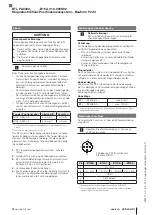
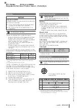
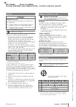
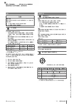
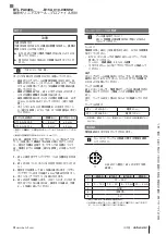
Pin assignment of S92 (view from 

above on BTL)

Pin …-B15AA… …-B15A1… …-B15AE… …-B15A5…

1

10…30 V

2

0…10 V

10…0 V

4…20 mA

20…4 mA

3

GND

1)

4

Unassigned

2)

5

0 V

1) Reference potential for supply voltage and EMC-GND.
2) Unassigned leads that are not used can be connected to the GND on 

the controller side but not to the shield.

Summary of Contents for BTL PA0400 Series

Page 1: ...0400 ____ B15A_010 000S92 deutsch Montageanleitung english Assembly instructions fran ais Notice de montage italiano Istruzioni di montaggio espa ol Instrucciones de montaje portugu s Instru es de mon...

Page 2: ...nd Erfahrungen sowie seiner Kenntnisse der einschl gigen Bestimmungen die ihm bertragenen Arbeiten beurteilen m gliche Gefah ren erkennen und geeignete Sicherheitsma nahmen treffen kann Der Betreiber...

Page 3: ...bzw schellen f hren 2 Nut des BTL in Richtung Positionsgeber ausrichten 3 BTL mit den Befestigungsschrauben auf dem Unter grund fixieren Schrauben in den Klammern bzw Schellen mit max 4 Nm festziehen...

Page 4: ...cal training knowledge and experience as well as knowledge of the relevant regulations allow them to assess the work assigned to them recognize possible hazards and take appropriate safety measures Th...

Page 5: ...or cuffs 2 Align BTL slot in the direction of the magnet s 3 Attach the BTL to the base tighten screws in clamps or cuffs to max 4 Nm tightening torque 4 Installing magnet accessory 5 Check orientatio...

Page 6: ...que par ses connaissances des dispositions sp cifiques r gissant son travail peut reconna tre les dangers potentiels et prendre les mesures de s curit ad quates Il est de la responsabilit de l exploit...

Page 7: ...ou colliers de fixation 2 Orienter le rainure du syst me BTL en direction du capteur de position 3 Fixer le syst me BTL au moyen des vis de fixation sur le support serrer les vis des brides ou des col...

Page 8: ...istica alle proprie conoscenze ed esperienze e alla propria conoscenza delle disposizioni in materia sono in grado di giudicare i lavori a loro affidati di riconoscere eventuali pericoli e di adottare...

Page 9: ...il BTL nei fermagli o nelle fascette di fissaggio 2 Orientare la scanalatura del BTL in direzione del datore di posizione 3 Fissare il BTL con le viti di fissaggio sul fondo serrare le viti nei ferma...

Page 10: ...as como a sus conocimientos de las disposiciones pertinentes puede valorar los trabajos que se le encargan detectar posibles peligros y adoptar medidas de seguridad adecuadas El explotador es respons...

Page 11: ...ranura del BTL en el sentido del sensor de posici n 3 Fijar el BTL con los tornillos de fijaci n sobre el fondo apretar los tornillos de los clips o de las abrazaderas con un valor m x de 4 Nm 4 Mont...

Page 12: ...onhecimentos experi ncia e conhecimentos da regulamenta o aplic vel s o capazes de avaliar os trabalhos que lhe sejam confiados reconhecer os poss veis riscos e tomar medidas de precau o adequadas O o...

Page 13: ...har a ranhura do BTL na dire o do encoder de posi o 3 Fixar o BTL superf cie com os parafusos de fixa o apertar os parafusos nos grampos ou nas bra adeiras com um torque m ximo de 4 Nm 4 Insira o enco...

Page 14: ...A_010 000S92 BTL PLC Mitgeltende Dokumente www balluff com BTL C 55 4 10 8 21 A 28 16 37 6 4 2 B 5 28 2 BTL6 A 3800 21 C 55 4 5 21 A B 18 28 16 37 6 4 2 BTL6 A 3801 21 60 60 60 50 5 5 30 18 37 55 4 M1...

Page 15: ...TL B C B1 C BTL6 A 3800 2 4 8 mm2 5 mm BTL6 A 3801 2 4 8 mm2 5 mm 1 2 6 8 mm BTL 1 BTL 2 BTL 3 BTL 4 Nm 4 5 BTL 2 3 BTL EMC BTL 85 BTL BTL BTL B15AA A1 30 m1 BTL B15AE A5 100 m1 1 3 1 4 2 5 S92 BTL B1...

Page 16: ...____ B15A_010 000S92 BTL SPS Balluff www balluff com BTL C 55 4 10 8 21 A 28 16 37 6 4 2 B 5 28 2 BTL6 A 3800 21 C 55 4 5 21 A B 18 28 16 37 6 4 2 BTL6 A 3801 21 60 60 60 50 5 5 30 18 37 55 4 M12x1 70...

Page 17: ...B C B1 C BTL6 A 3800 2 4 8 mm2 5 mm BTL6 A 3801 2 4 8 mm2 5 mm 1 2 6 8 mm BTL 1 BTL 2 BTL 3 BTL 4 Nm 4 5 BTL 2 3 BTL EMV BTL 85 BTL BTL BTL B15AA A1 30 m1 BTL B15AE A5 100 m1 1 3 1 4 2 5 S92 BTL B15A...

Page 18: ...____ B15A_010 000S92 BTL PLC Balluff www balluff com BTL C 55 4 10 8 21 A 28 16 37 6 4 2 B 5 28 2 BTL6 A 3800 21 C 55 4 5 21 A B 18 28 16 37 6 4 2 BTL6 A 3801 21 60 60 60 50 5 5 30 18 37 55 4 M12x1 70...

Page 19: ...B C B1 C BTL6 A 3800 2 4 8 mm2 5 mm BTL6 A 3801 2 4 8 mm2 5 mm 1 2 6 8 mm BTL 1 BTL 2 BTL 3 BTL 4 Nm 4 5 BTL 2 3 BTL EMC BTL 85 BTL BTL BTL B15AA A1 30 m1 BTL B15AE A5 100 m1 1 3 1 4 2 5 S92 BTL B15A...

Page 20: ...0 ____ B15A_010 000S92 BTL Balluff www balluff com BTL C 55 4 10 8 21 A 28 16 37 6 4 2 B 5 28 2 BTL6 A 3800 21 C 55 4 5 21 A B 18 28 16 37 6 4 2 BTL6 A 3801 21 60 60 60 50 5 5 30 18 37 55 4 M12x1 702...

Page 21: ...L BTL A 10 B BTL C B1 C BTL6 A 3800 2 4 8 2 5 BTL6 A 3801 2 4 8 2 5 1 2 6 8 BTL 1 BTL 2 BTL 3 BTL 4 4 5 BTL 2 3 BTL EMV BTL 85 BTL BTL BTL B15AA A1 30 1 BTL B15AE A5 100 1 1 3 1 4 2 5 S92 BTL B15AA B1...

Page 22: ...hengshan Rd 8F Building A Yunding International Commercial Plaza 200125 Pudong Shanghai Phone 86 400 820 0016 Fax 86 400 920 2622 service cn balluff com cn DACH Service Center Germany Balluff GmbH Sch...

Reviews: