26
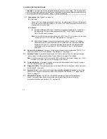
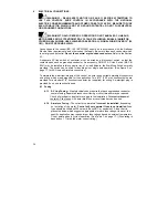
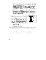
When Jumper J1 is placed in the "TRQ" position, the drive will control motor torque as a
linear function of main potentiometer setting. If the motor load exceeds the torque
setting, the motor will stall, the Overload LED will light, and the drive will apply a constant
preset torque based on the potentiometer setting. The Overload LED will light when the
load torque approaches the current limit set point. The torque limits are set via jumper J4
and the CL trimpot.
Note: When operating in the
Torque Mode, Jumper
J5 must be in the
"NTCL" position or
drive will shut down
when CL Timer times
out. Reference Section
6.5, on page 27.
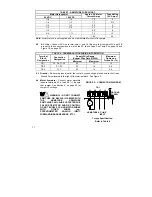
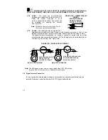
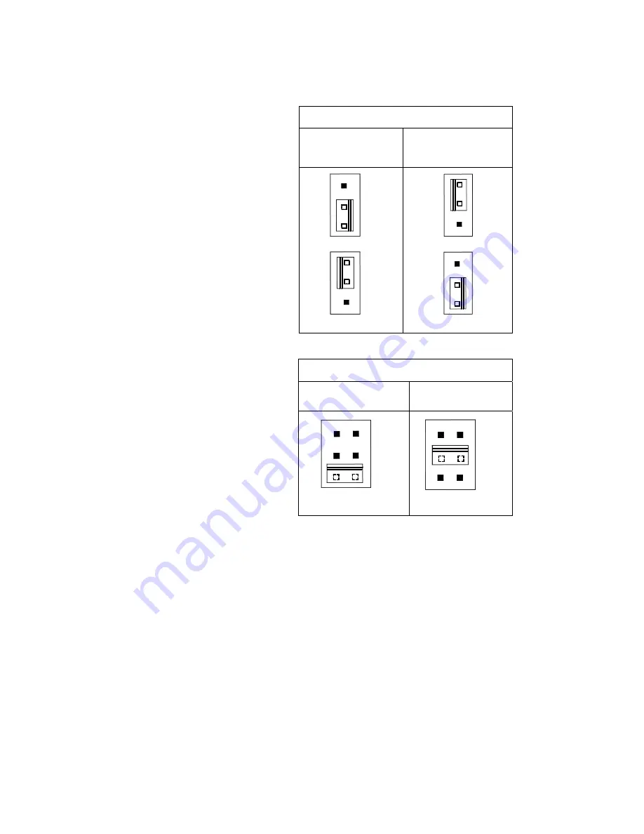
6.2 J2A, J2B – Input AC Line
Voltage –
Select proper input
line voltage 115VAC or
230VAC by placing
both
J2A
and J2B in the correct
corresponding
positions,
"115V" or
“
230V.”
See
Figure 17 and Table 11 on
page 27.
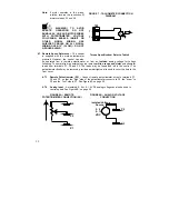
6.3
J3 – Armature Voltage
Output and Tach-Generator
Feedback –
Select the
desired armature voltage by
placing J3 in the proper
position “90V” for 90 –
130VDC motors and “180V"
for 180 – 220 VDC motors. For 115VAC line input the
armature voltage must be set to “90V.” See Figure 18.
For 230VAC line input, the
Armature voltage is normally
set to"180V". However, it is
also possible to operate in a
Step-Down Mode (90 –
130VDC motor with a
230VAC line) by setting J3 to
"90". However, reduced
performance may result.
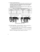
If tach-generator feedback is
to be used, J3 must be placed
in the "T" position and an
external DC tach-generator
must be connected. See
Section 4.6, on page 18 and
Section
6.6, on page 28, for
additional information.
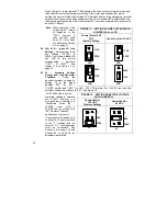
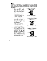
FIGURE 17 - SETTING AC LINE VOLTAGE WITH
JUMPER J2A and J2B
Control Set for 230
VAC
(Factory Setting
Control Set for 115 VAC
J2A
J2B
115V
115V
230V
230V
J2B
J2A
115V
230V
115V
230V
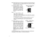
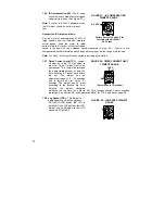
FIGURE 18 - SETTING ARMATURE VOLTAGE
WITH JUMPER J3
Control Set for
180 VDC
(Factory Setting)
Control Set for
90 VDC
J3
T
90V
180V
T
90V
180V
J3
Summary of Contents for NEMA-4X
Page 37: ...37 Notes...
Page 38: ...38 Notes...

