21
WARNING DO NOT USE START/STOP, INHIBIT OR ENABLE FUNCTIONS AS A
SAFETY DISCONNECT. USE ONLY AN AC LINE DISCONNECT FOR THAT PURPOSE.
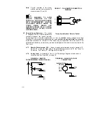
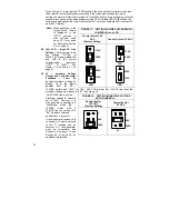
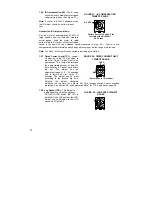
4.7.4 Inhibit –
The control can be electronically
stopped and started with the Inhibit circuit. To
"Stop" the control, Terminals I1 & I2
must be connected as shown. The control can
be
restarted
by
opening
the
contact.
See Figure 10A.
Note:
The Inhibit Circuit is not isolated. Do not
common or ground inhibit leads.
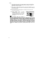
4.7.5
Enable
–
The control can also be started and
stopped with an Enable circuit (the Enable circuit functions opposite to that of the
inhibit circuit; inhibit: open to start, close to stop, Enable: open to stop, close to start).
The Enable function is established by wiring a contact in series with the violet
potentiometer lead connected to terminal P3. The Enable circuit is not isolated. Do not
common or ground wiring. See Figure 10B.
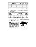
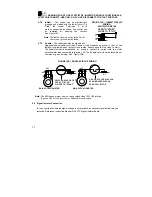
FIGURE 10B – ENABLE CIRCUIT WIRING
P3
SWITCH,RELAY OR FET
OPEN TO "STOP"
CLOSED TO "START"
MAIN POTENTIOMETER
VLT
A SOLID STATE RELAY CAN
ALSO BE USED WITH AN
OPEN COLLECTOR
MAIN POTENTIOMETER
VLT
P3
Note: The MIN speed trimpot must not be set higher than 70% CW rotation
(Approx. 2:00 o'clock position) or Enable will not function.
4.8 Signal
Isolator
Connection
In the event that an isolated signal voltage is not available, an optional signal isolator may be
installed. Reference Instruction Manual, MN1373. Signal Isolator Board.
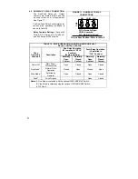
FIGURE 10A – INHIBIT CIRCUIT
WIRING
SWITCH OR RELAY
OPEN TO"START"
CLOSE TO "STOP"
I1
I2
Summary of Contents for NEMA-4X
Page 37: ...37 Notes...
Page 38: ...38 Notes...

