background image


11 


SAFETY NOTICE 
 

 WARNING

 - 

STATEMENT INDICATES A POTENTIALLY HAZARDOUS SITUATION 

WHICH, IF NOT AVOIDED, COULD RESULT IN INJURY OR DEATH.  


CAUTION

 - Statement indicates a potentially hazardous situation which, If not avoided, could result in 

damage to property.  


Note - Additional information that is not critical to the installation or operation. 


 WARNING! 

– 

READ SAFETY NOTICE ON PAGE 11 BEFORE ATTEMPTING TO USE 

THIS CONTROL. WIRE CONTROL IN ACCORDANCE WITH THE NATIONAL ELECTRIC CODE 
REQUIREMENTS AND OTHER CODES THAT APPLY. BE SURE TO FUSE EACH CONDUCTOR 
WHICH IS NOT AT GROUND POTENTIAL. DO NOT FUSE NEUTRAL OR GROUNDED 
CONDUCTORS.  


 WARNING! – DO NOT CONNECT SWITCHES OR RELAYS IN SERIES WITH THE 

ARMATURE. ARMATURE SWITCHING CAN CAUSE CATASTROPHIC FAILURE OF MOTOR 
AND/OR CONTROL.  


 WARNING! TO AVOID ERRATIC OPERATION DO NOT BUNDLE AC LINE AND 

MOTOR WIRES WITH POTENTIOMETER, VOLTAGE FOLLOWING, ENABLE, INHIBIT OR 
OTHER SIGNAL WIRING. USE SHIELDED CABLES ON ALL SIGNAL WIRING OVER 12" (30 CM) 
– DO NOT GROUND SHIELD. 


 WARNING DO NOT USE START/STOP, INHIBIT OR ENABLE FUNCTIONS AS A          

         SAFETY DISCONNECT. USE ONLY AN AC LINE DISCONNECT FOR THAT PURPOSE. 


 WARNING! DO NOT USE THIS DRIVE IN AN EXPLOSIVE ENVIRONMENT. AN 

EXPLOSION CAN CAUSE SERIOUS OR FATAL INJURY. THIS DRIVE IS NOT  EXPLOSION 
PROOF. 


  WARNING!  DO  NOT  ADJUST  TRIMPOTS  WITH  MAIN  POWER  ON  IF  POSSIBLE.  IF 

ADJUSTMENTS ARE MADE WITH POWER ON, INSULATED ADJUSTMENT TOOLS MUST BE 
USED AND SAFETY GLASSES MUST BE WORN. HIGH VOLTAGE EXISTS IN THIS CONTROL. 
ELECTROCUTION AND/OR FIRE CAN RESULT IF CAUTION IS NOT EXERCISED. SAFETY 
WARNING MUST BE READ AND UNDERSTOOD BEFORE PROCEEDING. 


 WARNING! READ SAFETY NOTICE ON PAGE 11 BEFORE ATTEMPTING TO 

OPERATE THE CONTROL OR SEVERE INJURY OR DEATH CAN RESULT. FAILURE TO 
FOLLOW THE SAFETY NOTICE, MAY RESULT IN ELECTRIC SHOCK, FIRE OR EXPLOSION. 

Summary of Contents for NEMA-4X

Page 1: ...Installation and Operation Manual NEMA 4X IP65 For Catalog Numbers BC154 and BCWD140 MN705 SCR DC MOTOR CONTROL...

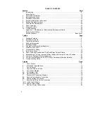
Page 2: ...8 7 Armature Fuse Chart 17 8 Terminal Block Wiring 17 9 Field Connections 18 10 Drive Operating Condition and Run Fault Relay Contact Status 22 11 Relationship of AC Line Input and Motor Voltage with...

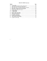
Page 3: ...oad Torque Mode 25 17 Setting AC Line Voltage with Jumper J2A and J2B 26 18 Setting Armature Voltage with Jumper J3 26 19 J5 Jumper Position 27 20 J6 Jumper Position 28 21 J7 Jumper Position 29 22 Min...

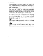
Page 4: ...tions for AC line voltage 230 115 DC armature voltage 180 90 and feedback type Armature Tach Generator Standard features include armature fusing fuse sold separately electronic start stop Switch and a...

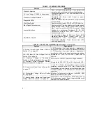
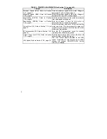
Page 5: ...Description J1 Speed Torque Mode Jumper Refer to Section 6 1 on page 23 In SPD position the motor speed is adjustable in accordance with the main speed potentiometer setting In TRQ position the motor...

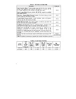
Page 6: ...ime for the motor to decelerate from full speed to zero speed Current Limit CL Refer to Section 7 2 5 on page 31 Sets the maximum amount of DC current that the motor can draw This determines the amoun...

Page 7: ...BC157 Auto Manual Switch Kit Allows for switching between Auto Man mode when the BC145 Signal isolator is installed BC145 sold separately BC158 ON OFF AC Line Switch This option is desirable if a pos...

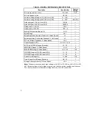
Page 8: ...ed 1 Speed regulation Tachometer Feedback Set Speed 1 AC Line Voltage Regulation Base Speed 0 5 Current Ranges ADC 2 5 5 0 7 5 10 ACCEL and DECEL Ranges Seconds 0 1 15 1 MIN SPEED Range Base Speed 0 3...

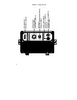
Page 9: ...START STOP SWITCH SECTION 4 7 3 PAGE 20 HOLE PLUG OPTIONAL FWD BRK REV SWITCH TABLE 4 PAGE 7 SPEED ADJUST POTENTIOMETER SECTION 4 7 PAGE 19 LED INDICATORS SECTION 9 PAGE 34 DC MOTOR SPEED CONTROL NEMA...

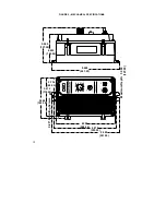
Page 10: ...SPEED CONTROL RUN STOP START NEMA 4X IP 65 0 10 20 30 40 50 60 70 80 90 100 JOG REV FWD BRK 5 000 127 00 4 055 103 00 9 488 241 00 5 866 149 50 5 472 139 00 8 228 209 00 8 875 225 50 9 488 241 00 0 2...

Page 11: ...N DO NOT BUNDLE AC LINE AND MOTOR WIRES WITH POTENTIOMETER VOLTAGE FOLLOWING ENABLE INHIBIT OR OTHER SIGNAL WIRING USE SHIELDED CABLES ON ALL SIGNAL WIRING OVER 12 30 CM DO NOT GROUND SHIELD WARNING D...

Page 12: ...BE SURE TO FOLLOW ALL INSTRUCTIONS CAREFULLY FIRE OR ELECTROCUTION CAN RESULT DUE TO IMPROPER USE OF THIS PRODUCT READ SAFETY WARNING CAUTION 1 Adjusting the CL above 150 of motor rating can cause ove...

Page 13: ...ld wires 90 volt motors with 50 volt fields and 180 volt motors with 100 volt fields to F1 and L1 See Section 4 on page 16 2 2 Speed or Torque Mode Jumper J1 is factory set for speed control operation...

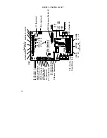
Page 14: ...n 4 P1 Section 4 TB2 Section 4 Shunt Motors Only F1 Section 4 J6 Section 6 T1 Power Transformer AC LINE F1 F2 A1 A2 L1 L2 Section 4 FIELD MOTOR CON2 J3 F1 TB1 Section 4 Section 6 Inset L1B L1A A1B J2A...

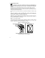
Page 15: ...heat dissipation If full rating is required a minimum enclosure size of 12 W x 24 H x 12 D should be used See Figure 2 on page 10 for dimensional specifications Front Cover The BC154 BCWD140 case is d...

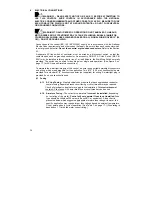
Page 16: ...tch can be wired for double pole or single pole operation See Figure 5 on page 17 for AC Line and Armature connection To maintain the watertight integrity of the control be sure to use suitable watert...

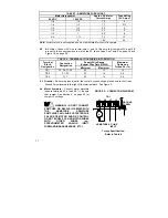
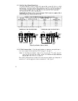
Page 17: ...on Designation Minimum Maximum Maximum Tightening Torque lb in TB1 A1 A2 L1 L2 22 12 12 TB2 F1 F2 22 14 3 5 TB3 T T 22 14 3 5 4 3 Ground Be sure to ground earth the control by connecting a ground wire...

Page 18: ...0 F1 F2 115 90 50 F1 L1 230 180 200 F1 F2 230 180 100 F1 L1 230 90 100 F1 L1 Step Down Operation See Section 6 3 on page 26 FIGURE 6A FULL VOLTAGE FIELD FIGURE 6B HALF VOLTAGE FIELD F1 F2 FIELD ARMATU...

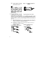
Page 19: ...te orange and violet potentiometer leads from terminals P1 P2 and P3 The leads may be taped and left in the control The potentiometer itself may be removed provided a watertight seal is used to cover...

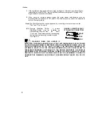
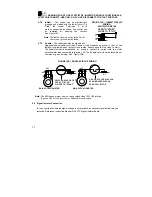
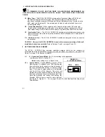
Page 20: ...stalled by disconnecting the wires from the Start Com and Stop terminals and reconnecting the terminals toa remotely mounted switch See Figure 9 WARNING WHEN THIS JUMPER IS INSTALLED THE DRIVE AND MOT...

Page 21: ...to stop close to start The Enable function is established by wiring a contact in series with the violet potentiometer lead connected to terminal P3 The Enable circuit is not isolated Do not common or...

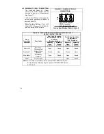
Page 22: ...tting Fault Relay Operation J5 Installed in TCL Position Drive Operating Condition Description Normally Open Contact Normally Closed Contact Normally Open Contact Normally Closed Contact Power Off Mai...

Page 23: ...ols are designed for use on machine applications CAUTION Be sure the BC 154 BCWD140 is used within its maximum ratings Follow all installation instructions carefully Refer to Sections 3 and 4 on pages...

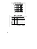
Page 24: ...100 100 90 80 70 60 50 40 30 20 10 0 POTENTIOMETER ROTATION MOTOR OUTPUT SPEED FIGURE 14 PRESET MOTOR SPEED vs MOTOR LOAD SPEED MODE LOWER SET SPEED HIGHER SET SPEED 0 10 20 30 40 50 60 70 80 90 100 1...

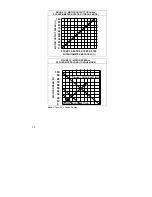
Page 25: ...ER ROTATION TORQUE MODE 0 10 20 30 40 50 60 70 80 90 100 100 90 80 70 60 50 40 30 20 10 0 POTENTIOMETER ROTATION MOTOR OUTPUT SPEED FIGURE 16 MOTOR SPEED vs APPLIED MOTOR LOAD TORQUE MODE MOTOR SPEED...

Page 26: ...27 6 3 J3 Armature Voltage Output and Tach Generator Feedback Select the desired armature voltage by placing J3 in the proper position 90V for 90 130VDC motors and 180V for 180 220 VDC motors For 115...

Page 27: ...tting can be readjusted using the CL trimpot See Table 12 and Section 7 2 5 on page 31 TABLE 12 JUMPER J4 SETTING vs MOTOR HORSEPOWER MOTOR HORSEPOWER RANGE JUMPER J4 SHOWN IN FACTORY SETTING 90 VDC 1...

Page 28: ...ive is manually turned off If non timed CL operation is desired move jumper J5 from the factory set TCL position to the NTCL position The NTCL position must be used when operating in the Torque Mode 6...

Page 29: ...e sure the main speed adjust potentiometer is fully CCW 7 1 Verify Correct Direction of Motor Rotation WARNING BE PREPARED TO STOP THE DRIVE WITH THE STOP SWITCH OR BY DISCONNECTING THE AC POWER IF MO...

Page 30: ...ltage of the drive This sets the maximum speed of the motor Use the MAX trimpot to change the factory setting See Figure 23 Adjust the MAX trimpot as follows a Rotate Main Potentiometer to maximum spe...

Page 31: ...pproximately fifteen 15 seconds 2 The Deceleration circuit works when rotating the main speed pot in the CCW direction or when opening the P3 lead of the main pot or when placing the Start Stop switch...

Page 32: ...Timed Current Limit to be operational This trimpot determines the approximate amount of time the drive will stay in Current Limit before trip out The trimpot has an adjustment range of 5 15 seconds a...

Page 33: ...if the control was running and INHIBIT is asserted or ENABLE is opened C Overload Indicator OL When the motor is loaded to the current limit setpoint CL setpoint is established by the setting and the...

Page 34: ...will drive the motor at full speed only If the Forward Brake Reverse switch is used provision must be made to reverse the polarity of the tachometer leads when the control is switched to Reverse TABLE...

Page 35: ...y be set too low OL LED indicator is illuminated Rapid Acceleration change will cause the OL LED to illuminate Verify potentiometer setting Check to see if the AC Line connections have been made Power...

Page 36: ...Horsepower Resistor into the two 2 pins located under the resistor R69 Each of the current selection values are now divided by 10 See Table 13 below TABLE 13 CURRENT LIMIT SETTINGS with 05 OHM PLUG I...

Page 37: ...37 Notes...

Page 38: ...38 Notes...

Page 39: ...EXAS HOUSTON 4647 PINE TIMBERS SUITE 135 HOUSTON TX 77041 PHONE 713 895 7062 FAX 713 690 4540 DALLAS 3040 QUEBEC DALLAS TX 75247 PHONE 214 634 7271 FAX 214 634 8874 UTAH SALT LAKE CITY 2230 SOUTH MAIN...

Page 40: ...venience or consequential damage including injury to any person caused by items of our manufacture or sale Some states do not allow the exclusion or limitation of incidental or consequential damages s...

Reviews: