
18
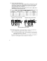
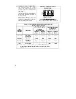
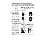
4.5 Field [For Shunt Wound Motors Only]
Do not use terminals F1 and F2 for any other purpose than to power the field on a shunt
wound motor. Connect motor shunt field to terminals F1 and F2 for 180 VDC motors with
200 VDC fields. For motors with half voltage fields (180 VDC motors with 100 VDC fields),
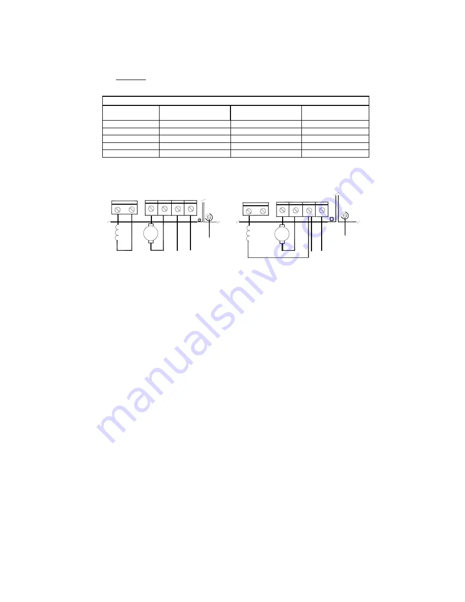
connect field to terminals F1 and L1. See Table 10 for a summary of Field Connections.
See Figures 6A and 6B for field wiring diagrams.
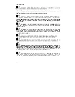
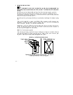
CAUTION! Shunt-Wound motors may be damaged if field remains energized without
motor rotating for an extended period of time.
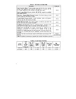
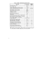
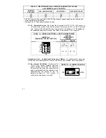
TABLE 9 – FIELD CONNECTIONS (Shunt Wound Motors Only)
AC LINE
VOLTAGE (VAC)
MOTOR VOLTAGE
FIELD VOLTAGE
(VDC)
FIELD
CONNECTION
115 90
100 F1,
F2
115 90
50 F1,
L1
230 180
200 F1,
F2
230 180
100 F1,
L1
230 90*
100 F1,
L1
* Step Down Operation (See Section 6.3, on page 26)
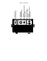
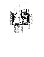
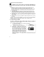
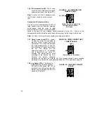
FIGURE 6A – FULL VOLTAGE FIELD
FIGURE 6B – HALF VOLTAGE FIELD
F1 F2
FIELD
+ -
+ -
ARMATURE
AC LINE
INPUT
TB2
TB1
A1 A2 L1 L2
M
GROUND
SCREW
+ -
+ -
M
TB1
FIELD
TB2
AC LINE
INPUT
ARMATURE
F1 F2
GROUND
SCREW
A1 A2 L1 L2
Torque Specification: Refer to Table 8
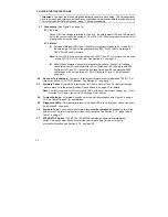
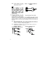
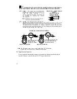
4.6 DC Tach-Generator Input –
If Tach-Generator feedback is required, an analog tach signal
must be connected to the terminal block TB3. See Figure 7, on page 19.
Note: For Tach-Generator feedback, Jumper J3 must be set to the "T" position, jumper J6
must be set for the proper tach voltage, and the IR COMP must be set to minimum
(ccw) position. See Section 6.6, on page 28.
Connect the Tach-Generator so that when the motor rotates the positive tach voltage lead is
connected to T+ and the negative tach lead is connected to T– (See Figure 7).
Summary of Contents for NEMA-4X
Page 37: ...37 Notes...
Page 38: ...38 Notes...


