17
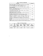
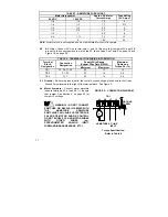
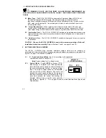
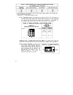
TABLE 7 - ARMATURE FUSE CHART
Motor Horsepower
90 VDC
180 VDC
Approx. DC Motor
Current Amps
Fuse Rating
(AC Amps)
1/8 1/4 1.3
2
1/6 1/3 1.7
2
½
1/4 1/2 2.5
4
1/3 3/4 3.3
5
1/2 1 5.0
8
3/4
1
½
7.5 12
1 2
10.0
20
Note: Armature fuse is not supplied and must be installed for control to operate.
4.2 AC
Line
–
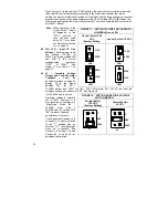
Connect AC Line to terminals L1 and L2. (Be sure that Jumpers J2A and J2B
are set to the correct position to match the AC line voltage. See Table 9 on page18 and
Figure 18, on page 26.
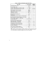
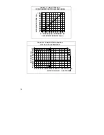
TABLE 8 - TERMINAL BLOCK WIRING INFORMATION
Supply Wire Gauge
(Copper Wire Only (AWG))
Terminal
Block
Designation
Connection
Designation
Minimum Maximum
Maximum
Tightening
Torque (lb – in)
TB1
A1, A2, L1, L2
22
12
12
TB2 F1,
F2
22
14
3.5
TB3 T+,
T-
22
14
3.5
4.3 Ground –
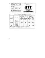
Be sure to ground (earth) the control by connecting a ground wire to the Green
Ground Screw located to the right of the terminal block. See Figure 5.
4.4 Motor Armature –
Connect motor armature
leads to terminals A1 (+) and A2 (–). Be sure
that jumper. See Section 6, on page 23 for
Jumper J3 settings.
WARNING! – DO NOT CONNECT
SWITCHES OR RELAYS IN SERIES WITH
THE ARMATURE. ARMATURE
SWITCHING CAN CAUSE CATASTROPHIC
FAILURE OF MOTOR AND/OR CONTROL.
DO NOT BUNDLE AC AND MOTOR WIRES
WITH OTHER WIRES (e.g.,
POTENTIOMETER, ANALOG INPUT,
FORWARD-BRAKE-REVERSE, ETC.)
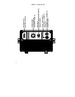
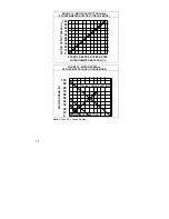
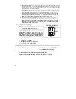
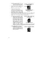
FIGURE 5 – CONNECTION DIAGRAM
GROUND
SCREW
A1 A2 L1 L2
TB1
M
+
-
ARMATURE AC LINE
INPUT
Torque Specification:
Refer to Table 8
Summary of Contents for NEMA-4X
Page 37: ...37 Notes...
Page 38: ...38 Notes...

