background image

Moisture Target Series 6 User’s Manual

53

Chapter 3. Operation and Programming

3.6.8 Setting the Volume Mixing Ratio

Note:

Setting the 

Volume Mixing Ratio

 is an optional feature, available only if the ppmv software version was 

purchased.

Note:

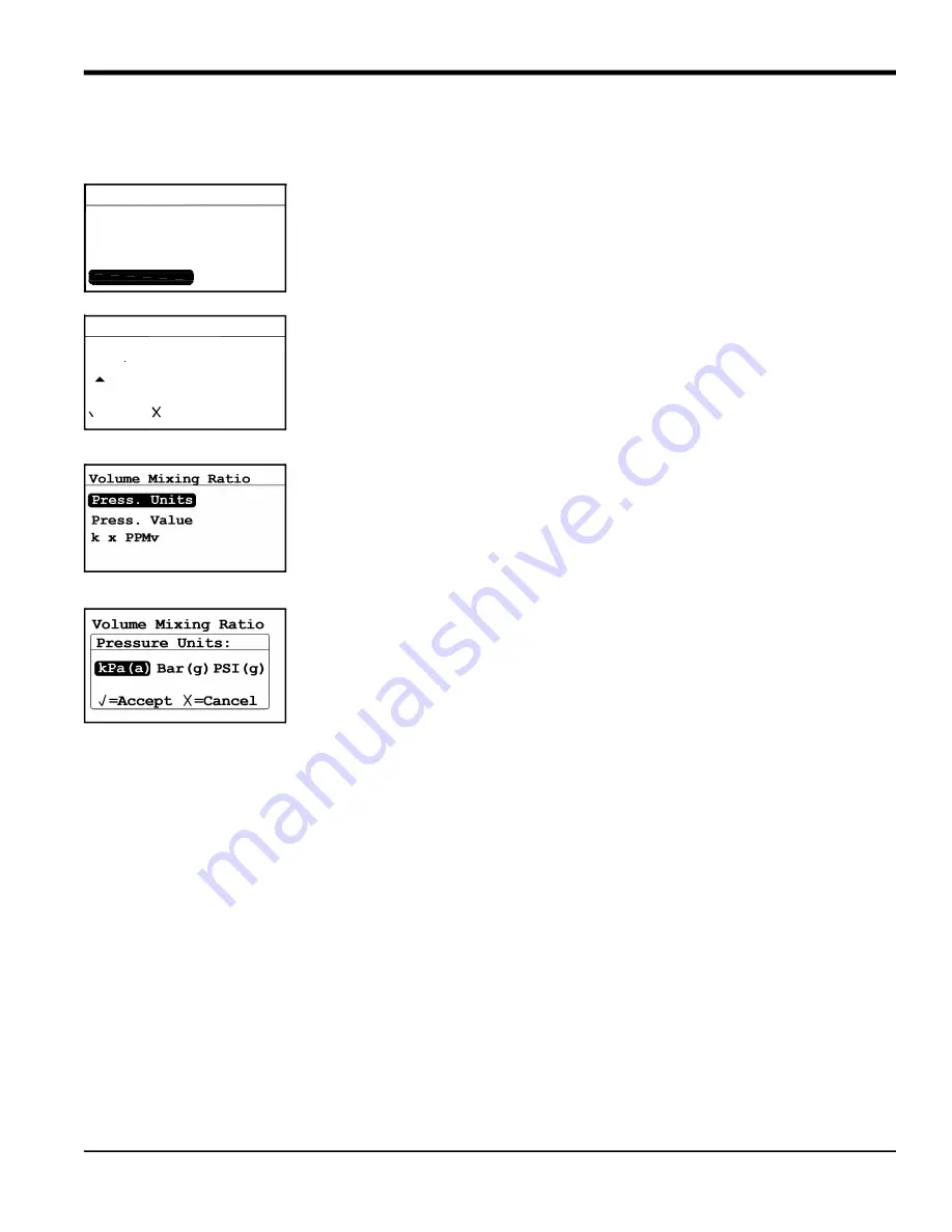
To set the volume mixing ratio, from the 

Settings Menu

 select 

V/V Ratio

 and press 

Enter


. The following screen appears.

Note:

 To access the 

Cal Data 

menu, the 

User Passcode

 is required (see section 3.6.1 on 

page 43).

Use the left and right arrow keys to select each digit to be changed and the up and 

down arrow keys to increase or decrease its value. Once the passcode has been 
entered, press 

Enter


 and the following screen appears.

3.6.8.1

Setting the Pressure Units

To set the pressure units, select 

Press. Units 

and press 

Enter


. The following screen 

appears.

Use the left and right arrow keys to select each digit to be changed and the up and 
down arrow keys to increase or decrease its value. Press 

Enter


 to save (or 

Cancel


to keep the previous value), and return to the previous menu.

Settings Menu

V/V Ratio...

AutoCal...

Fault Alm...

Cal Data...

Clock...
Probes
DpC Offset


0000

/=Save  =Cancel

User Passcode:


Summary of Contents for Panametrics MTS6

Page 1: ...panametrics com Process Analyzers 910 291 E October 2021 Moisture Target Series 6 User s Manual...

Page 2: ......

Page 3: ...or more registered trademarks of Baker Hughes Company and its subsidiaries in one or more countries All third party product and company names are trademarks of their respective holders Process Analyze...

Page 4: ...ii no content intended for this page...

Page 5: ...t for each installation Auxiliary Equipment Local Safety Standards The user must make sure that he operates all auxiliary equipment in accordance with local codes standards regulations or laws applica...

Page 6: ...nd the environment In order to avoid the dissemination of those substances in our environment and to diminish the pressure on the natural resources we encourage you to use the appropriate take back sy...

Page 7: ...Accessing the Menus 34 3 1 3 Entering Numeric Values 35 3 2 Setting Up the Display 36 3 2 1 Selecting Primary Units 36 3 2 2 Setting Decimal Places 37 3 2 3 Contrast 37 3 3 Setting Up the Output 38 3...

Page 8: ...70 3 6 11 Setting a Constant DP C Offset 71 3 7 Viewing System Information 72 3 7 1 Checking the ID 72 3 7 2 Checking the Status 72 3 7 3 Checking the Software Version 72 3 7 4 Checking the Probe 72...

Page 9: ...ent The MTS6 accepts any calibration range provided with Panametrics probes see Chapter 5 Specifications for more information It comes equipped with two standard alarm relays one fault alarm relay and...

Page 10: ...ith the process The MTS6 uses any Panametrics M Series see Figure 2 or a VeriDri probe see Figure 3 to measure dew point temperature in C or F The sensor assembly is secured to the probe mount and is...

Page 11: ...mple system installing the probe into the sample system wiring the input power wiring the probe and alarm connections WARNING To ensure safe operation the MTS6 must be panel mounted and operated as de...

Page 12: ...by switch S1 on the main PC board Complete these steps to check or reset switch S1 see Figure 8 WARNING Never connect line voltage or any other power input to the recorder output terminals 1 Make sure...

Page 13: ...nstallation Figure 6 Sliding the Cover Back Figure 7 Lifting the Cover 4 Locate switch S1 see Figure 8 highlighted area CAUTION Use proper ESD grounding prior to changing the switch 5 Set switch S1 to...

Page 14: ...Chapter 2 Installation 6 Moisture Target Series 6 User s Manual Figure 8 Switch S1 on the Main PC Board 6 After setting the switch replace the cover and reinsert the rear enclosure screw...

Page 15: ...d flat panel using the panel gasket and both mounting brackets provided 2 3 1 Basic Mounting To mount the MTS6 in a panel with a basic 94 mm 3 69 x 46 mm 1 81 opening refer to the following figures an...

Page 16: ...Cutout 4 Behind the panel insert the mounting brackets into the side holes provided see Figure 12 Figure 12 Installing the Mounting Brackets 5 Hold the chassis and lock each mounting bracket in place...

Page 17: ...ion 2 3 2 Adapter Plate Mounting Some customers may need to retrofit an MTS6 into a cut out sized for Panametrics s previous OEM panel mount hygrometers MTS5 MTS4 or PanaDry models The previous genera...

Page 18: ...nstalling the Adapter Plate Gasket 2 Fit the adapter plate into the panel cutout see Figure 17 Figure 17 Inserting the Adapter Plate 3 Behind the panel place the metal backing plate over the four adap...

Page 19: ...compression and tighten the nuts until the gap is 0 032 0 002 Figure 19 Securing the Assembly to the Panel Figure 20 Plate Assembly Mounting Complete Now mount the MTS6 using steps 1 6 in Basic Mounti...

Page 20: ...Chapter 2 Installation 12 Moisture Target Series 6 User s Manual Figure 22 MTS6 Installation with Adapter Plate Front 2 4 Mounting the Sample System Figure 23 Typical Sample System...

Page 21: ...obe is mounted in a cylindrical container called the sample cell which is included as part of your sample system Standard M2 probes and VeriDri probes are mounted into the sample system or process lin...

Page 22: ...cable WARNING To ensure safe operation the MTS6 must be installed and operated as described in this manual Also be sure to follow all applicable local safety codes and regulations for installing elec...

Page 23: ...Moisture Target Series 6 User s Manual 15 Chapter 2 Installation Figure 27 MTS6 Wiring Diagram...

Page 24: ...igure 30 on page 17 and complete the following steps 1 Insert the end of probe cable with the bayonet type connector onto the probe and twist the shell clockwise until it snaps into a locked position...

Page 25: ...Target Series 6 User s Manual 17 Chapter 2 Installation Figure 30 Bottom Connector Removed Figure 31 Making Probe Cable Connections to the Connector Figure 32 Reinserting the Connector into the Termin...

Page 26: ...ri cable connect the probe to the lower terminal block pins 10 11 12 and 13 on the back of the MTS6 see Table 1 and Figure 35 and Figure 36 on page 19 IMPORTANT To maintain good contact at the termina...

Page 27: ...tom Connector Removed Figure 35 Wiring the Cable to the Connector Figure 36 Reinserting the Connector into the Terminal Block Note When there is a No Link error for the VeriDri check the wiring to ens...

Page 28: ...gle pole double throw contact set that contains the following contacts Normally Open NO Common C Normally Closed NC 2 6 4 1 Connecting the High Low Alarms A and B IMPORTANT Ensure that the power is of...

Page 29: ...2 works in the opposite way The alarm is energized to close the contact during ordinary operation and the alarm is de energized to open the contact when there is a fault IMPORTANT Ensure that the pow...

Page 30: ...e Installed 2 6 6 Installing the DC Power Cable The DC power cable with 14 to 26 AWG wires is supplied by the customer Use the following instructions to connect the cable to the MTS6 Figure 40 MTS6 Re...

Page 31: ...r of the DC power cable by approximately 3 8 3 Insert each wire into the appropriate slot and chassis and tighten each screw to secure them in place IMPORTANT Ensure that the chassis ground connection...

Page 32: ...Chapter 2 Installation 24 Moisture Target Series 6 User s Manual...

Page 33: ...e unlocked To unlock the screen press Cancel Enter Cancel Note In most instances use the Enter key to save an entry and or move ahead to the following screen use the Cancel key to reject an entry and...

Page 34: ...ght arrow keys to select the digit to change The digit selected will be indicated with a Use the up and down arrow keys to increment or decrement the digit Note If incrementing or decrementing a digit...

Page 35: ...play and press Enter The following screen appears 3 2 1 Selecting Primary Units To select units for the primary display select Unit Select and press Enter The following screen appears Use the arrow ke...

Page 36: ...mal symbol if possible Use the arrow keys to change the number of decimal places and press Enter or press Cancel if no changes are necessary The screen returns to the Display Menu 3 2 3 Contrast To mo...

Page 37: ...screen appears 3 3 2 Selecting Output Units From the Output Menu select Units and press Enter The following screen appears Use the arrow keys to select the unit type and press Enter The screen returns...

Page 38: ...r to save or Cancel to keep the previous value and return to the Output Menu 3 3 4 Changing the Upper Output Span To adjust the upper output span from the Output Menu select Upper and press Enter A sc...

Page 39: ...will appear Use the left and right arrow keys to select each digit to be changed and the up and down arrow keys to increase or decrease its value Press Enter to save or Cancel to keep the previous va...

Page 40: ...l cause the MTS6 to output 20 000 mA on the output being trimmed The output value should then be read using the connected recorder SCADA equipment or DVM Enter the value read from the connected equipm...

Page 41: ...et up and press Enter The display returns to the Alarm Menu 3 4 2 Selecting Alarm Status To select the alarm status from the Alarm Menu select Status and press Enter The following screen appears Use t...

Page 42: ...rchased PPMv mg m3 g m3 and kg m3 will be available 3 4 4 Selecting an Alarm Type To change the alarm type from the Alarm Menu select Type and press Enter A screen similar to the following appears Use...

Page 43: ...6 User s Manual 35 Chapter 3 Operation and Programming 3 4 5 How the Alarm Types Work Figure 45 Example of Alarm Types Out Band Trip Trip In Band Reset Reset Upper Hysteresis Lower Setpoint Trip Reset...

Page 44: ...nd down arrow keys to increase or decrease its value Press Enter to save or Cancel to keep the previous value and return to the Alarm Menu 3 4 7 Changing the Lower Alarm Span To adjust the lower alarm...

Page 45: ...ow keys to select Reset or Trip and press Enter If Reset was selected the message Alarm is RESET appears If Trip was selected the message Alarm is Tripped appears Press Cancel to return to the Alarm M...

Page 46: ...he arrow keys to select the unit to be represented by 1 and press Enter The screen returns to the Units to Log menu Note If the VeriDri probe is being used FH replaces MH Note If the ppmv software ver...

Page 47: ...een returns to the Set Log Params menu 3 5 2 4 Setting Log Status Flags Note The flags used to identify the log status are as follows To turn log status flags on or off from the Set Log Params menu se...

Page 48: ...e is any previous log running paused it will need to be closed Once closed the closed log file cannot be resumed To create a new log from the Manage Log Files menu select New Log and press Enter A scr...

Page 49: ...r The following screen appears Select Resume and press Enter the screen returns to the Manage Log Files menu Note When a log is resumed the Manage Log Files menu displays the Pause Close option again...

Page 50: ...w be removed from the MTS6 Note Physically removing the MicroSD card from the MTS6 without performing the eject routine below may result in data loss This will not result in damage to either the Micro...

Page 51: ...ion 3 6 1 above Use the left and right arrow keys to select each digit to be changed and the up and down arrow keys to increase or decrease its value Once the passcode has been entered press Enter and...

Page 52: ...and press Enter The following screen appears To change the status of the range error alarm select Yes or No and press Enter The screen returns to the Fault Alarm menu Press Cancel to return to the Set...

Page 53: ...Cancel to keep the previous value and return to the AutoCal Settings menu To accept or reject AutoCal select Cal Now and press Enter A screen similar to the following appears To accept AutoCal select...

Page 54: ...ct Num of Points and press Enter The following screen appears Use the left and right arrow keys to select each digit to be changed and the up and down arrow keys to increase or decrease its value Pres...

Page 55: ...ase its value Press Enter to save or Cancel to keep the previous value and return to the Edit MH DP Cal menu 3 6 4 4 Setting the Dew Point Calibration To set up the dew point calibration highlight Edi...

Page 56: ...Once the passcode has been entered press Enter and the following screen appears If you are using a VeriDri probe the FH DPCal will be highlighted Press Enter The following screen appears 3 6 5 1 Sele...

Page 57: ...ss Cancel to return to the Read FH DP Calibration menu 3 6 5 3 Reading the DP Value To view the DP value highlight Read DP Value and press Enter The following screen appears The DP value is for viewin...

Page 58: ...ues will alter the accuracy of the unit measurements To update calibration data from the Settings Menu select Cal Data and press Enter The following screen appears Note To access the Cal Data menu the...

Page 59: ...d down arrow keys to increase or decrease its value Once the changes have been made press Enter The screen returns to the Edit Cal Refs menu 3 6 6 2 Setting the Calibration Low Reference To update low...

Page 60: ...page 43 Use the left and right arrow keys to select each digit to be changed and the up and down arrow keys to increase or decrease its value Once the passcode has been entered press Enter a screen si...

Page 61: ...ft and right arrow keys to select each digit to be changed and the up and down arrow keys to increase or decrease its value Once the passcode has been entered press Enter and the following screen appe...

Page 62: ...n arrow keys to increase or decrease its value Press Enter to save or Cancel to keep the previous value and return to the previous menu 3 6 8 3 Setting the k x PPMv Multiplier To set the k x PPMv mult...

Page 63: ...wing screen 3 6 9 1 Setting the Hour To change the hour select Hour and press Enter The following screen appears Use the left and right arrow keys to select each digit to be changed and the up and dow...

Page 64: ...and press Enter The following screen appears Use the left and right arrow keys to select each digit to be changed and the up and down arrow keys to increase or decrease its value Press Enter to save...

Page 65: ...l default the output and alarm settings to DPC Also the default fault trip point values will be set along with the default output range values From the Settings Menu select Probes and press Enter The...

Page 66: ...ise they will work only within the calibrated range of the sensor Note Use the following procedure to set the DP C Offset From the Settings Menu select DpC Offset and press Enter The following screen...

Page 67: ...About MTS6 menu press Cancel 3 7 2 Checking the Status To check the status of the MTS6 from the About menu select Status and press Enter A screen similar to the following appears The information incl...

Page 68: ...the Probe To check the probe details from the About menu select Probe and press Enter A screen similar to one of the following appears Data when using an M Series probe To return to the About MTS6 men...

Page 69: ...enu select Wiring and press Enter A screen similar to the following appears To return to the Main Menu press Cancel twice 3 8 Locking the Menu To lock the ability to make changes to the menu select LO...

Page 70: ...Chapter 3 Operation and Programming 62 Moisture Target Series 6 User s Manual Your passcode is 2719 Please remove this page and put it in a safe place for future reference...

Page 71: ...apter please consult Panametrics for help CAUTION Do not attempt to troubleshoot the MTS 6 beyond the instructions in this chapter If you do you may damage the unit and void the warranty This chapter...

Page 72: ...t time for the system to equilibrate Response Reads too wet during dry down conditions or too dry in wet up conditions Action Change the flow rate A change in dew point indicates the sample system is...

Page 73: ...Moisture Target Series 6 User s Manual 65 Chapter 4 Service and Maintenance...

Page 74: ...anel When necessary use the procedure below to clean the front panel You will need the following Clean lint free cloth Cleaning solution soap and warm water To clean the front panel 1 Moisten the clot...

Page 75: ...s are available for the high low alarms set to trip at any level within the range of the instrument and programmable from the front panel Alarm Setpoint Repeatability 0 1 C dew point MicroSD Supports...

Page 76: ...egree II 5 2 Moisture Measurement Sensor Type thin film aluminum oxide moisture sensor probe Moisture Probe Compatibility compatible with all Panametrics M Series aluminum oxide moisture probes and Ve...

Page 77: ...Moisture Target Series 6 User s Manual 69 Chapter 5 Specifications Accuracy 2 C from 65 to 60 C 3 C from 110 to 66 C Repeatability 0 5 C from 65 to 60 C 1 0 C from 110 to 66 C...

Page 78: ...Chapter 5 Specifications 70 Moisture Target Series 6 User s Manual...

Page 79: ...Chapter A Outline and Installation Drawings Moisture Target Series 6 Hygrometer User s Manual71 Chapter A Outline and Installation Drawings...

Page 80: ...get Series 6 Hygrometer User s Manual Figure 46 MTS6 Outline and Mounting ref dwg 712 1550 121 78 4 79 92 60 3 65 118 38 4 66 5 50 22 57 2 24 104 4 09 45 1 77 93 60 3 69 46 1 81 Notes 1 Dimensions are...

Page 81: ...Hygrometer User s Manual73 Figure 47 MTS6 Optional Adapter Plates ref dwg 705 1297 82 3 23 150 5 91 93 3 66 46 1 81 A A 123 4 84 55 2 17 138 5 43 75 2 95 NUT 4X M3 GASKET METAL PLATE BEZEL 18 0 71 8...

Page 82: ...ef dwg 702 1015 DC Power Terminal Block 1 2 3 NO NC NO NC NO NC C C C FAULT ALARM ALARM A ALARM B RTN OUT GREEN RED C D PROBE BLUE BROWN BLACK WHITE 10 11 12 13 14 15 16 17 18 VERIDRI AC UNIT DC UNIT...

Page 83: ...Chapter B Menu Maps Moisture Target Series 6 Hygrometer User s Manual93 Chapter B Menu Maps...

Page 84: ...Eject Card AutoCal Fault Alarm Cal Data MH DP Cal Edit DP C Select Cal Point Edit MH Passcode Protected DP F Status Type Set Fault Alarm OFF ON Fault Relay Alarm on Range Error TRIPPED RESET Passcode...

Page 85: ...Set Fault Alarm OFF ON Fault Relay Alarm on Range Error TRIPPED RESET Passcode Protected Options Yes No Fault Alarm is Test Reset Trip Select Status Set Alarm Status OFF ON Units Select Unit Type DP C...

Page 86: ...Chapter B Menu Maps 96Moisture Target Series 6 Hygrometer User s Manual no content intended for this page...

Page 87: ...ore removing the MicroSD Card refer to section 3 5 4 Ejecting the SD Card on page 42 to first stop the data log 1 Locate the memory card in the lower center of the rear panel and pull the flexible cov...

Page 88: ...98Moisture Target Series 6 Hygrometer User s Manual 2 Push in the memory card until it clicks and pull it from the MTS6 chassis see Figure 53 and Figure 54 Figure 53 Pushing in on the MicroSD Card Fi...

Page 89: ...d Moisture Target Series 6 Hygrometer User s Manual99 3 Plug the memory card into a card reader and insert the reader into a computer see Figure 55 and Figure 56 Figure 55 Plugging the Reader into a P...

Page 90: ...ure Target Series 6 Hygrometer User s Manual C 2 Accessing the Files 1 From the PC open My Computer and find the device see Figure 57 Figure 57 Locating the Device 2 Click on Removable Disk and a scre...

Page 91: ...r C Reading the MicroSD Card Moisture Target Series 6 Hygrometer User s Manual101 Figure 58 List of Log Files 3 Click on the desired file and a screen similar to Figure 59 appears Figure 59 Log File N...

Page 92: ...e MicroSD Card 102Moisture Target Series 6 Hygrometer User s Manual 4 Log files can be opened with a text editor Open Excel and select Open Figure 60 Importing Log Files to Excel Figure 61 Selecting t...

Page 93: ...es 5 Open the file by clicking twice on the number Note Ensure that the file type equals all types The following screen appears see Figure 62 Figure 62 Excel Import Wizard 1 6 Follow the directions on...

Page 94: ...ding the MicroSD Card 104Moisture Target Series 6 Hygrometer User s Manual Figure 63 Excel Import Wizard 2 7 Set the desired data delimiters and click on Next The following screen appears see Figure 6...

Page 95: ...e Target Series 6 Hygrometer User s Manual105 Figure 64 Excel Import Wizard 3 8 Select each column and set the data format for it see Figure 64 9 When the setup is complete click on Finish and a scree...

Page 96: ...Chapter C Reading the MicroSD Card 106Moisture Target Series 6 Hygrometer User s Manual Figure 65 Successful Excel Import The log file is now properly formatted for graphing or analysis...

Page 97: ...where no hazardous live wires are exposed See Figure 49 for dimensions Figure 49 MTS6 Non Enclosure Package Outline ref dwg 712 1687 2 Ground the MTS6 baseplate using the provided ground lug 3 Connec...

Page 98: ...76 Moisture Target Series 6 User s Manual...

Page 99: ...uropean Compliance 83 F Fault Alarm Connecting 29 Description 29 Setting 54 Setting Options 56 Testing 56 Fault Relay Type Setting 55 G Gasket 9 Adapter Plate 12 I ID Checking 72 Information Setting 5...

Page 100: ...Recorder Output Wiring 4 Replacing the Probe 79 Return Policy 96 S Safety Auxiliary Equipment iii General Issues iii Personal Equipment iii Sample Cell 17 Sample System Mounting 17 SD Card Ejecting 5...

Page 101: ...termines that the equipment was defective the warranty period is one year from delivery for electronic or mechanical failures one year from delivery for sensor shelf life If Panametrics determines tha...

Page 102: ...f Panametrics Sensing instructs you to send your instrument to a service center it must be shipped prepaid to the authorized repair station indicated in the shipping instructions 3 Upon receipt Paname...

Page 103: ...61326 2 3 2006 EN 61010 1 2012 Overvoltage Category II following the provisions of the 2004 108 EC EMC and 2006 95 EC Low Voltage Directives The unit listed above and any ancillary equipment supplied...

Page 104: ...Warranty 2 Moisture Target Series 6 User s Manual no content intended for this page...

Page 105: ......

Page 106: ...uct and company names are trademarks of their respective holders 910 219 E Customer Support Centers U S A The Boston Center 1100 Technology Park Drive Billerica MA 01821 U S A Tel 800 833 9438 toll fr...

Reviews: