12
12
Anchoring the Machine
•
Position the machine on a firm and level concrete floor and
maintain a safe operating distance around the machine.
•
Anchor the machine to the floor, as shown in the diagram,
using bolts and expansion plugs or sunken tie rods that
connect through holes in the base of the stand.
.31"
(7.87mm)
.50"
(12.7mm)
Summary of Contents for BP-3142NC
Page 3: ......
Page 16: ...13 13 GETTING TO KNOW YOUR MACHINE A B C D E G H I F J K L M N O ...
Page 24: ...21 21 Punch and Die Specifications ...
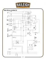
Page 28: ...25 25 ELECTRICAL SCHEMATIC ...
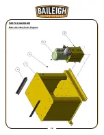
Page 29: ...26 26 PARTS DIAGRAMS Base Assembly Parts Diagram ...
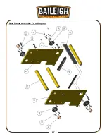
Page 30: ...27 27 Main Frame Assembly Parts Diagram ...
Page 31: ...28 28 Trunnion Bending Arm Assembly Parts Diagram ...
Page 32: ...29 29 Upper and Lower Ram Assembly Parts Diagram ...
Page 33: ...30 30 Back Stop Slide Shaft Assembly Parts Diagram ...
Page 34: ...31 31 Back Stop Assembly Parts Diagram ...
Page 35: ...32 32 Chain Tensioner Assembly Parts Diagram ...
Page 36: ...33 33 Cylinder Assembly Parts Diagram ...
Page 37: ...34 34 Travel Limit Assembly Parts Diagram ...
Page 38: ...35 35 Linkage Assembly Parts Diagram ...
Page 39: ...36 36 Cross Plate Assembly Parts Diagram ...
Page 40: ...37 37 Tooling Assembly Parts Diagram ...
Page 46: ...43 43 NOTES ...
Page 47: ...44 44 NOTES ...


