23
23
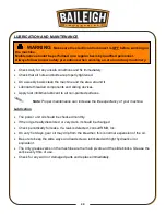
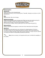
LUBRICATION AND MAINTENANCE
•
Check daily for any unsafe conditions and fix immediately.
•
Check that all nuts and bolts are properly tightened.
•
On a weekly basis clean the machine and the area around it.
•
Lubricate threaded components and sliding devices.
•
Apply rust inhibitive lubricant to all non-painted surfaces.
Note: Proper maintenance can increase the life expectancy of your machine.
Lubrication
•
The power unit oil should be checked monthly.
•
If the oil get really discolored or very dark, it should be changed
•
Check periodically for leaks. If a leak is detected, consult RMD, Inc.
•
On very hot days, gear oil may drip from the breather; this is normal expansion of the oil.
•
Be sure to keep the slide ways and lead screws lubricated with light hydraulic oil or
equivalent.
•
The only grease zerks on the machine are the main pivots and the slide blocks. Grease the
zerks every 8hrs of use.
•
Check for any worn or damaged parts and replace immediately.
WARNING:
Make sure the electrical disconnect is OFF before working on
the machine.
Maintenance should be performed on a regular basis by qualified personnel.
Always follow proper safety precautions when working on or around any machinery.
Summary of Contents for BP-3142NC
Page 3: ......
Page 16: ...13 13 GETTING TO KNOW YOUR MACHINE A B C D E G H I F J K L M N O ...
Page 24: ...21 21 Punch and Die Specifications ...
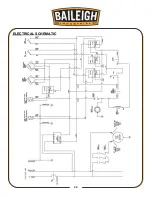
Page 28: ...25 25 ELECTRICAL SCHEMATIC ...
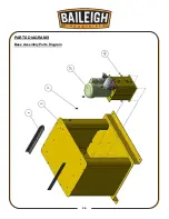
Page 29: ...26 26 PARTS DIAGRAMS Base Assembly Parts Diagram ...
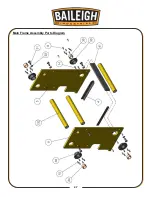
Page 30: ...27 27 Main Frame Assembly Parts Diagram ...
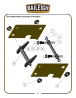
Page 31: ...28 28 Trunnion Bending Arm Assembly Parts Diagram ...
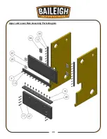
Page 32: ...29 29 Upper and Lower Ram Assembly Parts Diagram ...
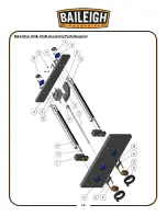
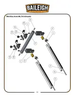
Page 33: ...30 30 Back Stop Slide Shaft Assembly Parts Diagram ...
Page 34: ...31 31 Back Stop Assembly Parts Diagram ...
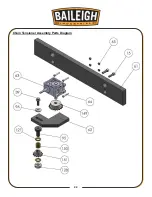
Page 35: ...32 32 Chain Tensioner Assembly Parts Diagram ...
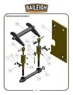
Page 36: ...33 33 Cylinder Assembly Parts Diagram ...
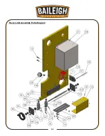
Page 37: ...34 34 Travel Limit Assembly Parts Diagram ...
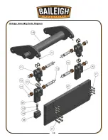
Page 38: ...35 35 Linkage Assembly Parts Diagram ...
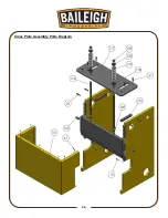
Page 39: ...36 36 Cross Plate Assembly Parts Diagram ...
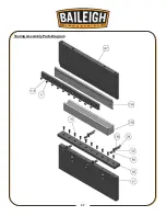
Page 40: ...37 37 Tooling Assembly Parts Diagram ...
Page 46: ...43 43 NOTES ...
Page 47: ...44 44 NOTES ...


