14
14
Item Name
Description
A
Back stop position
Handwheel.
This handwheel will adjust the position of the back stop
either near or far.
B
Ram Position
Handwheel.
This handwheel will set your bend angles by controlling the
ram end position.
C
Lower Die
Material is pressed onto/into the die to create the bend.
D
Upper Punch
Presses the material onto/into the die.
E
Return Springs
Assists in raising the ram to the up/retracted position.
F
Electrical Enclosure
Houses the electrical operating controls and connections.
G
Pressure Gauge
Displays the current operating pressure of the hydraulic
system.
H
Retract position
Handwheel.
This handwheel will adjust the retract distance of the ram.
Used to set the retract height just above the material being
bent.
I
Foot Pedals
Pressing the foot pedal will actuate the hydraulics which
will in turn cause the ram to move down or up as selected.
J
Main disconnect switch.
Turns on the main power to the machine
K
On push button (lighted)
When pressed, the hydraulic pump will start running.
L
Jog/ Auto switch
Selects which mode of operation.
In Jog the ram will only move when the foot pedal is
activated in either direction.
In Auto the ram will travel down with the foot pedal, but will
return automatically to the preset retract limit and stop.
M
E-Stop
Will disconnect all power to the motor circuit.
N
Position Counter
Displays the relative movement/adjustment dimension of
each axis.
O
Retract Position
Indicators
Indicates the approximate position of the ram and sets the
amount the ram will retract during operation.
Summary of Contents for BP-3142NC
Page 3: ......
Page 16: ...13 13 GETTING TO KNOW YOUR MACHINE A B C D E G H I F J K L M N O ...
Page 24: ...21 21 Punch and Die Specifications ...
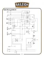
Page 28: ...25 25 ELECTRICAL SCHEMATIC ...
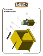
Page 29: ...26 26 PARTS DIAGRAMS Base Assembly Parts Diagram ...
Page 30: ...27 27 Main Frame Assembly Parts Diagram ...
Page 31: ...28 28 Trunnion Bending Arm Assembly Parts Diagram ...
Page 32: ...29 29 Upper and Lower Ram Assembly Parts Diagram ...
Page 33: ...30 30 Back Stop Slide Shaft Assembly Parts Diagram ...
Page 34: ...31 31 Back Stop Assembly Parts Diagram ...
Page 35: ...32 32 Chain Tensioner Assembly Parts Diagram ...
Page 36: ...33 33 Cylinder Assembly Parts Diagram ...
Page 37: ...34 34 Travel Limit Assembly Parts Diagram ...
Page 38: ...35 35 Linkage Assembly Parts Diagram ...
Page 39: ...36 36 Cross Plate Assembly Parts Diagram ...
Page 40: ...37 37 Tooling Assembly Parts Diagram ...
Page 46: ...43 43 NOTES ...
Page 47: ...44 44 NOTES ...


