15
15
ELECTRICAL
Motor Specifications
Your tool is wired for 220 volt, 60Hz alternating current. Before connecting the tool to the power
source, make sure the machine is cut off from power source.
Considerations
•
Observe local electrical codes when connecting the machine.
•
The circuit should be protected with a time delay fuse or circuit breaker with a amperage
rating slightly higher than the full load current of machine.
•
A separate electrical circuit should be used for your tools. Before connecting the motor to the
power line, make sure the switch is in the “OFF” position and be sure that the electric current
is of the same characteristics as indicated on the tool.
•
All line connections should make good contact. Running on low voltage will damage the
motor.
•
In the event of a malfunction or breakdown, grounding provides a path of least resistance for
electric current to reduce the risk of electric shock. This tool is equipped with an electric cord
having an equipment-grounding conductor and a grounding plug. The plug must be plugged
into a matching outlet that is properly installed and grounded in accordance with all local
codes and ordinances.
•
Improper connection of the equipment-grounding conductor can result in risk of electric
shock. The conductor with insulation having an outer surface that is green with or without
yellow stripes is the equipment-grounding conductor. If repair or replacement of the electric
cord or plug is necessary, do not connect the equipment-grounding conductor to a live
terminal.
CAUTION:
HAVE ELECTRICAL UTILITIES CONNECTED TO MACHINE BY
A CERTIFIED ELECTRICIAN!
Check if the available power supply is the same as listed on the machine nameplate.
WARNING:
Make sure the grounding wire (green) is properly connected
to avoid electric shock. DO NOT switch the position of the green grounding wire if
any electrical plug wires are switched during hookup.
WARNING:
In all cases, make certain the receptacle in question is
properly grounded. If you are not sure, have a qualified electrician check the
receptacle
.
Summary of Contents for BP-3142NC
Page 3: ......
Page 16: ...13 13 GETTING TO KNOW YOUR MACHINE A B C D E G H I F J K L M N O ...
Page 24: ...21 21 Punch and Die Specifications ...
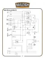
Page 28: ...25 25 ELECTRICAL SCHEMATIC ...
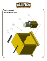
Page 29: ...26 26 PARTS DIAGRAMS Base Assembly Parts Diagram ...
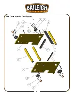
Page 30: ...27 27 Main Frame Assembly Parts Diagram ...
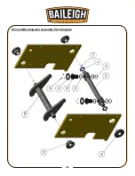
Page 31: ...28 28 Trunnion Bending Arm Assembly Parts Diagram ...
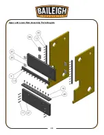
Page 32: ...29 29 Upper and Lower Ram Assembly Parts Diagram ...
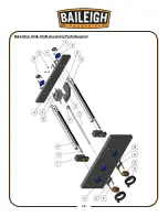
Page 33: ...30 30 Back Stop Slide Shaft Assembly Parts Diagram ...
Page 34: ...31 31 Back Stop Assembly Parts Diagram ...
Page 35: ...32 32 Chain Tensioner Assembly Parts Diagram ...
Page 36: ...33 33 Cylinder Assembly Parts Diagram ...
Page 37: ...34 34 Travel Limit Assembly Parts Diagram ...
Page 38: ...35 35 Linkage Assembly Parts Diagram ...
Page 39: ...36 36 Cross Plate Assembly Parts Diagram ...
Page 40: ...37 37 Tooling Assembly Parts Diagram ...
Page 46: ...43 43 NOTES ...
Page 47: ...44 44 NOTES ...


