


Tdvanced Mode
The advanced mode is intended users with knowledge of ultrasonic testing or when automatic settings are not appropriate .
To enter
Advanced Mode
, uncheck
Tutomatic Tnalysis Mode
. The manual settings reflect the automatic settings when the
wizard first opens .
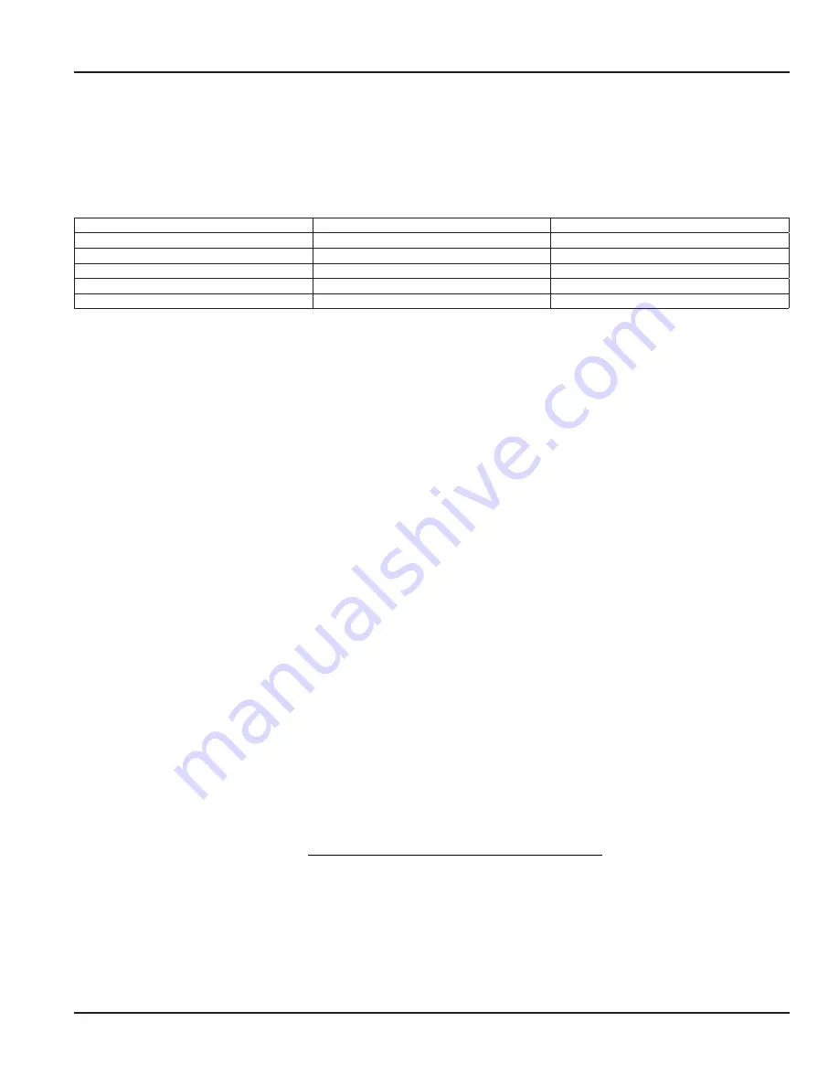
You can select the type of waveform and analysis from the pull-down menu . The first two digits represent how many signal
periods are transmitted, and the text indicates the analysis used in making the measurement:
01P Metal Tubing
1 Pulse
Tubing Mode
01P Thin Metal Pipe
1 Pulse
Thin Pipe Mode/ Pipe Mode
02P Generic Metals
2 Pulse
Pipe Mode
03P Plastics, Iron Pipe
3 Pulses
Pipe Mode
05P Thick Plastics, Ceramics, Mortar
5 Pulses
Pipe Mode
15P Very Thick
15 Pulses
Pipe Mode
Table 10: Pipe mode explanations
In
Pipe Mod
e, you must lock the reference signal
BEFORE
applying the transducer to the pipe . Ultrasonic transit time is
measured as the difference in time from the ultrasound leaving the transducer face to the first reflection from the fluid-pipe
interface . The reference is detected as the large peak below a timed threshold . The largest amplitude peak is used as the
first reflection .
In
Thin Pipe Mode
, you must also
lock
the reference signal
BEFORE
applying the transducer to the pipe .
In
Tubing Mode
, you must lock the reference
TFTER
applying the transducer is to the pipe . Ultrasonic transit time is measured
as the difference in time between two adjacent-in-time signal reflections . The largest amplitude peak is used as the reference,
Peak 1 and Peak 2 are any detected adjacent peaks to the reference .
Supplementary Information
• Expected error is about 1 .5% + 15 mils or 1 .5% + 0 .4 mm
• Measurement under 0 .1 in . or 2 .5 mm is difficult and requires special techniques (
Tubing Mode
and
Thin Pipe Mode
) .
• Does not measure liner thickness .
• May not always work on all materials, conditions and fluids .
• ◊ In thin metal and metal pipe modes, the reference can disappear from the display once the transducer is applied to
the pipe . This is why the reference is locked prior to placement on pipe .
[Pipe] Roughness (Numeric Value in Micro Feet)
Surface roughness is the measure if the small surface irregularities in the pipe surface and is composed of three components:
roughness, waviness and form . These are the result of the manufacturing process employed to create the surface .
Surface roughness average (Pipe R), also known as arithmetic average (AA) is rated as the arithmetic average deviation of the
surface valleys and peaks expressed in micro inches (µ inches) .
The DXN provides flow profile compensation in its flow measurement calculation . One of the components of that calculation
is roughness . The ratio of average surface imperfection as it relates to the pipe internal diameter is used in this compensation
algorithm and is found by using the following formula:
Pipe R
RMS Measurement of the Pipes Internal Wall Surface
Inside Dia
=
m
meter of the Pipe
OTEE:
N
A microinch (µ inch) is one millionth (1/1,000,000) of an inch .
If a pipe material was chosen from the Pipe Material list, a nominal value for relative roughness in that material is
automatically loaded .
If the pipe has a roughness value that differs from standard for the pipe type, a custom value can be entered using the
Roughness controls .
Setup Group
Page 47
November 2016
HYB-UM-00090-EN-04


