10
OPERATION
Power ON/OFF
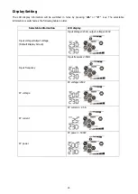
Once the unit has been properly installed and the batteries are connected well, simply press On/Off switch
(located on the display panel) to turn on the unit.
Operation and Display Panel
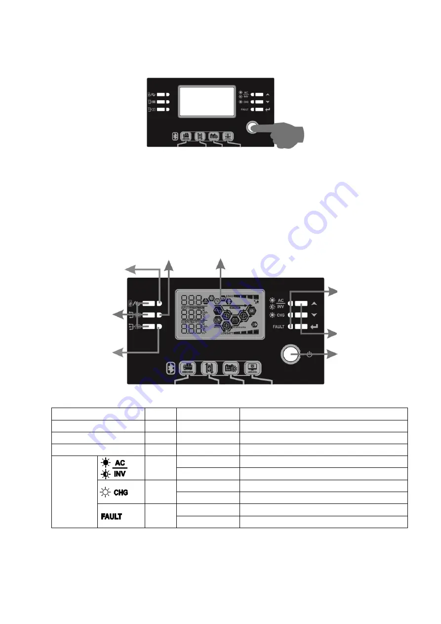
The operation and display panel, shown in below chart, is on the front panel of the inverter. It includes six
indicators, six function keys, on/off switch and a LCD display, indicating the operating status and input/output
power information.
LCD display
Indicators
LED Indicator
Color Solid/Flashing
Messages
Setting LED 1
Green
Solid On
Output powered by utility
Setting LED 2
Green
Solid On
Output powered by PV
Setting LED 3
Green
Solid On
Output powered by battery
Status
indicators
Green
Solid On
Output is available in bypass mode
Flashing
Output is powered by battery in inverter mode
Green
Solid On
Battery is fully charged
Flashing
Battery is charging.
Red
Solid On
Fault mode
Flashing
Warning mode
Status
indicators
Function keys
On/off switch
Function keys
Setting LED 3
Setting LED 1
Setting LED 2


