IPC960/IPC962/IPC964-525 Series U
ser’s Manual
Hardware Installation
66
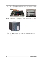
Step 12
Paste the Mylar on the vents of the system cover.
Step 13
Close the cover back to the chassis and fasten the screw. The installation
is complete.
Note: Please note the T4 FAN module kit supports IPC962 w/AX96205 and IPC960
w/AX96205 expansion box kit only.
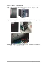
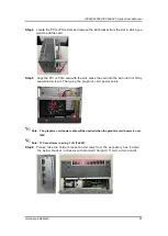
Note: Please note the power connector on the riser card can
’
t be used in IPC962
w/AX96205 and T4 fan module kit configuration.
Summary of Contents for IPC960-525 Series
Page 1: ...IPC960 525 series IPC962 525 series IPC964 525 series Industrial Computers User s Manual...
Page 17: ...IPC960 IPC962 IPC964 525 Series User s Manual Introduction 9 IPC964 525...
Page 99: ...IPC960 IPC962 IPC964 525 Series User s Manual AMI BIOS Utility 91 AMT Configuration...
Page 104: ...IPC960 IPC962 IPC964 525 Series User s Manual AMI BIOS Utility 96 PCI Subsystem Setting...
Page 109: ...IPC960 IPC962 IPC964 525 Series User s Manual AMI BIOS Utility 101 Memory Configuration...


