IPC960/IPC962/IPC964-525 Series U
ser’s Manual
Introduction
28
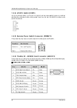
1.8.14 AT/ATX Switch (SSW1)
If you set AT/ATX switch to AT mode, the system will be automatically powered on without
pressing the soft power button during power input; we can use this switch to achieve auto
power on demand.
1.8.15 Remote Power Switch Connector (PWRBT1)
The system has one 2-pin connector output for remote power on/off switch.
Function
Description
Short(1-2)
Turn on/off system
Open
Keep system status
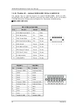
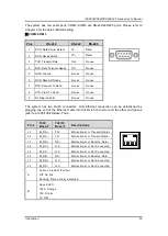
1.8.16 Flexible IO - COM I/O Card Connector (AX93511)
The system has an optional four serial port module. COM2~COM5 are RS-232/422/485 ports.
Please refer to Chapter 3 for the details of BIOS setting.
※
COM2,COM3,COM4,COM5
Pins
RS-232
RS-422
RS-485
1
DCD, Data Carrier Detect
TX-
Data-
2
RXD, Receive Data
TX+
Data+
3
TXD, Transmit Data
RX+
No use
4
DTR, Data Terminal Ready
RX-
No use
5
GND, Ground
No use
No use
6
DSR, Data Set Ready
No use
No use
7
RTS, Request To Send
No use
No use
8
CTS, Clear To Send
No use
No use
9
RI, Ring Indicator
No use
No use
Summary of Contents for IPC960-525 Series
Page 1: ...IPC960 525 series IPC962 525 series IPC964 525 series Industrial Computers User s Manual...
Page 17: ...IPC960 IPC962 IPC964 525 Series User s Manual Introduction 9 IPC964 525...
Page 99: ...IPC960 IPC962 IPC964 525 Series User s Manual AMI BIOS Utility 91 AMT Configuration...
Page 104: ...IPC960 IPC962 IPC964 525 Series User s Manual AMI BIOS Utility 96 PCI Subsystem Setting...
Page 109: ...IPC960 IPC962 IPC964 525 Series User s Manual AMI BIOS Utility 101 Memory Configuration...


