IPC960/IPC962/IPC964-525 Series U
ser’s Manual
Hardware Installation
54
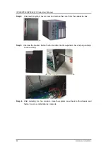
Step 4
Unscrew the system cover screw and remove the cover from the expansion box.
Step 5
Unscrew the bracket, fasten the fan module into the expansion box and plug cable(s)
to connector(s).
Step 6
After installing the fan module, close the system cover back to the chassis and
fasten the screw. Installation is complete.
Summary of Contents for IPC960-525 Series
Page 1: ...IPC960 525 series IPC962 525 series IPC964 525 series Industrial Computers User s Manual...
Page 17: ...IPC960 IPC962 IPC964 525 Series User s Manual Introduction 9 IPC964 525...
Page 99: ...IPC960 IPC962 IPC964 525 Series User s Manual AMI BIOS Utility 91 AMT Configuration...
Page 104: ...IPC960 IPC962 IPC964 525 Series User s Manual AMI BIOS Utility 96 PCI Subsystem Setting...
Page 109: ...IPC960 IPC962 IPC964 525 Series User s Manual AMI BIOS Utility 101 Memory Configuration...


