background image

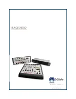
RAQ/DESQ 

Installation & User’s Guide

Manual Rev 1 - January 2012

p/n 1490-00086-001

Summary of Contents for DESQ

Page 1: ...RAQ DESQ Installation User s Guide Manual Rev 1 January 2012 p n 1490 00086 001...

Page 2: ...onformity is declared to those standards EN50081 1 EN50082 1 Important Safety Information Electrical Warning If the equipment is used in a manner not specified by the manufacturer the protection provi...

Page 3: ...re Keep moisture away from the ventilation openings in the top and front of the unit To avoid the possibility of electrical shock do not use this equipment when you are wet If you accidentally drop th...

Page 4: ...SQ and QORs are determined largely by software Periodic updates may become available to determine if this is the case visit our web site periodically or contact us for advice concerning whether a newe...

Page 5: ...hanks to all of the engineers architects and design ers that made this console a reality you know who you are cn Feedback is welcome At Axia we love to hear your feedback If you find anything in this...

Page 6: ...isplays 21 Show Profiles 21 Sources Channels and Faders 21 Mix Minus 21 GPIO 21 Software 22 Callouts and Operation 22 Source Specific Channel Controls 27 Control Room Operator Mic Channel 27 Control R...

Page 7: ...ger Menu 49 IO Manager Menu 49 Ethernet Switch settings Preconfigured 49 Chapter Seven Networking with DESQ and RAQ 52 Inputs 52 Outputs 53 Appendix A Specifications 55 Appendix B Block Diagrams 57 Ap...

Page 8: ...Introduction viii 2012 Axia Audio...

Page 9: ...ns of companies partnered with us to make innovative broadcast products that connect to Axia networks with just the click of an Ethernet cable And we conceived of some interesting new devices and appl...

Page 10: ...Introduction x 2012 Axia Audio Crimping the spade lugs the smell of soldering flux they ll be missed Not much...

Page 11: ...1 to configure IP address settings for your RAQ DESQ 5 Refer to the User s Manuals packed with any other Axia Audio nodes for information on how to configure IP addresses for these units What s Next...

Page 12: ...Getting Started 2 2012 Axia Audio Open box connect Seven pounds of pure power Who needs big consoles...

Page 13: ...cess the system window on the large OLED display Use PREVIEW knob to highlight rotate or select press Highlight and select the NETWORK option Highlight and select the IP ADDRESS option From this wind...

Page 14: ...lecting 1kHz Tone Above the MONITORS knob press the PGM 1 but ton so that you are monitoring Program 1 For channel 1 2 and 3 press the PGM 1 button to assign the channel to those mixes Press the ON bu...

Page 15: ...twork administrator if you are unsure about what address to use Each QOR requires a single fixed IP address The RAQ or DESQ control surfaces are controllers for the QOR so they share the same IP addre...

Page 16: ...nding NET lamp is unlit a problem with the network connection is indicated When a disconnected Ethernet link has been re estab lished the NET LED will blink with a 50 duty cycle for about 5 seconds as...

Page 17: ...ts These connectors use the standard wiring convention for 3 pin XLR audio connectors These connectors may have 48 volt Phan tom power enabled via the QOR s web page configura tion Please take appropr...

Page 18: ...includes the needed power CANBus connections for use in conjunction with your control surfaces The accessory CANBus port is an additional port that is available for future use Important Like any elect...

Page 19: ...o take effect Gateway settings on an QOR are not usually re quired however a valid gateway enables access to the QOR configuration remotely from outside your net work A gateway also facilitates the us...

Page 20: ...1 Setup and Connections 10 2012 Axia Audio In our youth we never dreamed that one day streams might not have water...

Page 21: ...web browser to the IP ad dress of your QOR When you connect to it you will be prompted for a user name and password By default the user name is user and there is no password First we ll walk through t...

Page 22: ...lding has always been tying data to audio sources Consider the wiring of analog line selector modules you needed a cable for the remote audio source a set of wires for a start closure another set for...

Page 23: ...PIO logic which can operate TALK TO functions from a remote producer s panel It also mutes CR monitors and Preview when ON CR Guest is used for any other guest mic in the con trol room Its associated...

Page 24: ...vewire has been se lected as your Source Input See Chapter 7 Livewire Networking for more on this Signal Mode Non Microphone Sources Determines whether source will be treated as a mono or stereo sourc...

Page 25: ...the channel on and off Fader Start follows the common European stan dard of activating the channel and associated ma chine logic when the fader is raised from Fader Start with Arm works just like the...

Page 26: ...ons for the Options control on each of the con sole s fader strips Available options will vary depend ing on the source type One setting may be defined as the Primary or live control which means that...

Page 27: ...e V Mode is a signal converter that allows you to ma nipulate some mono mode sources V Mode has one in put and one output thus creating one additional source V Mixer and V Mode outputs are assigned in...

Page 28: ...box that transforms your stereo stream into something else You may choose from any of the following options Pass Stereo Passes the Left and Right chan nels as is without modification Mono sum to L Cr...

Page 29: ...er to that Node s IP address instead 6 The GPIO setup screen uses the same method of assigning devices to ports as other Livewire de vices Pick a port to map your Phone channel s con tact closures to...

Page 30: ...2 Inputs and Outputs 20 2012 Axia Audio CAT 6 small and light yet sound and data pour forth What magic is this...

Page 31: ...the operator simply uses the source A fader s status display tells operators when a particu lar source has a mix minus output and even tells them which audio mix is being backfed RAQ DESQ will generat...

Page 32: ...out in a conventional manner with the monitor and ancillary controls located on the right side of the frame Let s look at each of these sections in detail 1 Channel ON Switch The ON key toggles the ch...

Page 33: ...s assigned to the Preview bus 4 Channel Information Display This OLED display interacts with the Channel Options control and the Soft key It is context sensitive and can dis play many different parame...

Page 34: ...When the channel is used in fader start mode pushing the fader all the way to the bottom of its travel turns the module off and sends appropri ate logic commands to source equipment Moving the fader u...

Page 35: ...ress the Profile key You can also push and hold the pro file key for 5 seconds to reload the current profile 11 Control Room Monitor Select Keys This group of keys selects the source that is delivered...

Page 36: ...ON or when Record Mode is active 16 Clock Key DESQ only Pressing this key toggles between AUTO and MANUAL modes for the count up timer AUTO allows it to be reset and started by any source starting th...

Page 37: ...e Preview speakers whenever the channel is On or if Pre view keys are selected Control Room Guest Microphone Channel There are often microphones in the Control Room other than the board operator s i e...

Page 38: ...codec source the OLED displays TALKBACK When the remote mute function is activated the OLED displays MUTED and all the channel outputs are muted until the command is released The mix minus output con...

Page 39: ...e QOR Web interface You will probably find that a combination of console setup capture and edit works best When you select any Show Profile you will enter the edit screen as shown in Figure 4 2 Notice...

Page 40: ...fault CR Monitor CR Headphones Preview Dim Gain 30 0 dB You may adjust the Dim Gain independently for CR Monitor CR Head phones This determines the amount of dimming that will be applied when Talkback...

Page 41: ...a second push cancels any individual Preview assignment Switchable Meter Source The second meter is a soft meter The desired default may be selected from the drop down menu Choices are Program 2 Phon...

Page 42: ...nal Talk and with no Operator mic loaded to a channel the operator can still engage Talk functions to backfeeds What s Next We have mentioned GPIO many times in the preced ing chapters Join us in Chap...

Page 43: ...hich type of device is assigned to it Back in Chapter 2 when you constructed a Source Profile for a telephone hybrid you defined the source type see Adding Backfeeds and GPIO to a Source Pro file This...

Page 44: ...Monitor 2 Lamp 3 Open Collector to Logic Com mon Return Illuminates when TALK TO MON2 is active MUTE Lamp 4 Open Collector to Logic Com mon Return Illuminates when MUTE is active TALK to PREVIEWED SOU...

Page 45: ...ollector to Logic Com mon Return Illuminates when TALK is active MUTE Lamp 4 Open Collector to Logic Com mon Return Illuminates when MUTE is active NOT CONNECTED 5 POWER COMMON Source Common 7 Logic C...

Page 46: ...ONITOR 2 Lamp 3 Open Collector to Logic Com mon Return Illuminates when TALK to MON2 is active MUTE Lamp 4 Open Collector to Logic Com mon Return Illuminates when MUTE is active TALK to PREVIEWED SOUR...

Page 47: ...when PREVIEW is ON START Pulse 4 Open Collector to Logic Com mon Return A 100 msec pulse when the channel status changes from OFF to ON STOP Pulse 5 Open Collector to Logic Com mon Return A 100 msec...

Page 48: ...Com mon Return Illuminates when TALK is active MUTE Lamp 4 Open Collector to Logic Com mon Return Illuminates when MUTE is active TALK to SOURCE Lamp 5 Open Collector to Logic Com mon Return Illumina...

Page 49: ...RT Pulse 4 Open Collector to Logic Com mon Return A 100 ms PULSE is sent when channel is first turned ON or when PVW is first selected STOP Pulse 5 Open Collector to Logic Com mon Return A 100 ms PULS...

Page 50: ...turn Illuminates when PREVIEW is active TALK TO EXT Lamp 4 Open Collector to Logic Com mon Return Illuminates when Talk to External is active TALK to CR Active Lamp 5 Open Collector to Logic Com mon R...

Page 51: ...on Return Illuminates when PREVIEW is ON START Pulse 4 Open Collector to Logic Com mon Return A 100 ms PULSE sent when channel is first turned ON STOP Pulse 5 Open Collector to Logic Com mon Return A...

Page 52: ...port will follow the logic associated with that channel this will be used for CR monitor logic SPECIFIED INPUT Define an input port and the port will follow the logic of that input 3 If using the LIV...

Page 53: ...ing audio source to a GPIO port automagically configures the port for the type of device supplying the audio and send the appropriate logic commands to that port when the source is assigned to a chann...

Page 54: ...e so an external relay controlled by the GPO may need to be used to provide a dry contact closure to the external device Please note that this section is provided as a jump start introduction to Axia...

Page 55: ...le of this sort of virtual GPIO operation is triggering the TALK TO EXT command and EXT PREVIEW command of the CR Monitor logic What s Next When you re ready join us in Chapter 6 for a com prehensive...

Page 56: ...as information pertaining to the active software load A sample of this screen is shown in figure 6 1 Additional information displayed may in clude QOR software version info including the current ac ti...

Page 57: ...oftware choice Upload Image From time to time Axia makes new software packages available for down load from AxiaAudio com downloads Use the Browse and Upload Image buttons to install new software as d...

Page 58: ...of a backup file name might be QOR 192 168 0 200 2012 03 25_17 13 xml Restore Settings To restore a previous QOR backup use the browse button to locate the back up and then select Restore Log Log Hist...

Page 59: ...For a thorough discussion of this screen and how to configure GPIO please refer to Chapter 5 Configuring GPIO Remote The remote function available through the web in terface gives you many of the same...

Page 60: ...twork switch The remainder of ports are 100 Mbps ports for your Livewire enabled de vices Four of the ports also include PoE Power over Ethernet which can be used to power de vices that utilize this t...

Page 61: ...6 Advanced Controls 51 2012 Axia Audio Mimicking nature streams combine to form anew many become one...

Page 62: ...wire IP Audio System Design Refer ence and Primer which provides an excellent discussion of IP Audio and how standard Ether net can be used to transport real time broad cast audio in a studio environm...

Page 63: ...ernal generated QOR sources including PGM 1 2 CR Monitor CR Headphones Preview Talk to CR Talk to External and Auto Backfeed VMix or VMode outputs Name Override Allows you to specify a name 16 charact...

Page 64: ...address numerically lower than any of your QOR units or Ethernet edge switches This function of the IGMP standard ensures that the multicast querier is handled by the core switch if one exists The qu...

Page 65: ...ut 102 dB referenced to 0 dBFS 105 dB A weighted to 0 dBFS Analog Input to Digital Output 105 dB referenced to 0 dBFS Digital Input to Analog Output 103 dB referenced to 0 dBFS 106 dB A weighted Digit...

Page 66: ...o Allows board operator mic to talk to other devices a logic command is associated Talk to CR Audio Mono Allows the Talk to CR audio mix to drive an external destination Monitor related Inputs Type Co...

Page 67: ...Appendix B Block Diagrams Figure B 1 Block Diagram Operator Microphone Revised March 2012 MUTE OPERATOR MICROPHONE SOURCE FADER PAN TALK TO X TALK TO X POST FADER PRE FADER PREVIEW PREVIEW PHONE PROG...

Page 68: ...udio Figure B 2 Block Diagram Guest Microphone Block Diagrams Revised March 2012 MUTE STUDIO GUEST MICROPHONE SOURCE FADER PAN POST FADER PRE FADER PREVIEW PREVIEW PHONE PROGRAM 1 PGM 1 ON PROGRAM 2 P...

Page 69: ...Revised March 2012 Figure B 3 Block Diagram Line Source Block Diagrams LINE SOURCE MODE STEREO LEFT RIGHT SUM L R MUTE FADER PAN JOIN TALK TO X TALK TO X POST FADER PRE FADER PREVIEW PREVIEW PHONE PRO...

Page 70: ...012 FEED TO PHONE SOURCE SUM TO LEFT SUM TO RIGHT TALK TO BOTH MODE TALK PHONE PHONE SOURCE MODE STEREO LEFT RIGHT SUM L R MUTE FADER PAN JOIN TALK TO X TALK TO X POST FADER PRE FADER PREVIEW PREVIEW...

Page 71: ...CODEC SOURCE SUM TO LEFT SUM TO RIGHT TALK LEFT ONLY MODE TALK PHONE CODEC SOURCE MODE STEREO LEFT RIGHT SUM L R MUTE FADER PAN JOIN TALK TO X TALK TO X POST FADER PRE FADER PREVIEW PREVIEW PHONE PROG...

Page 72: ...1 OUTPUT STEREO PGM 1 MIX PGM 2 PGM 2 OUTPUT STEREO PGM 2 MIX PHONE PHONE MIX PGM 1 METER PGM 2 METER VMIX1 IN 2 VMIX1 IN 3 VMIX1 IN 4 VMIX1 IN 5 INPUT 2 INPUT 3 INPUT 4 INPUT 5 VMIX1 IN 1 INPUT 1 FAD...

Page 73: ...L PREVIEW IN CR MON VOLUME TALK LEVEL DIM CR MON PREVIEW IN CR MON PREVIEW IN CR HP PGM 1 MIX CR PGM1 PGM 2 MIX CR PGM2 EXTERNAL 1 CR EXT1 EXTERNAL 2 CR EXT2 CR MONITOR OUTPUT TALK TO CR OUTPUT DIM LE...

Page 74: ...Appendix B Block DIagrams 64 2012 Axia Audio The cup steams sweet scent wafting lightly in the air Mmmmm it is Earl Grey...

Page 75: ...e address automatically from a pool Because Livewire devices are permanently attached and because it is more desirable to know the IP address attached to a particular node and perhaps assign them in s...

Page 76: ...Appendix D Worksheets 66 2012 Axia Audio Axia IP Address Assignment Worksheet IP Address Device Name Location Notes...

Page 77: ...Appendix D Worksheets 67 2012 Axia Audio Axia Audio Channel Assignment Worksheet SOURCES Channel ID Number Device Name Device Location Notes...

Page 78: ...Appendix D Worksheets 68 2012 Axia Audio Axia Audio Channel Assignment Worksheet DESTINATIONS Channel ID Number Device Name Device Location Notes...

Page 79: ...s agents or authorized dealers be liable for incidental or consequential damages or for loss damage or expense directly or indirectly arising from the use of any Product or the inability to use any Pr...

Page 80: ...Axia Audio a Telos Alliance Company 1241 Superior Ave Cleveland Ohio 44114 USA 1 216 241 7225 www AxiaAudio com...

Reviews: