CONNECTION AND SETUP
6
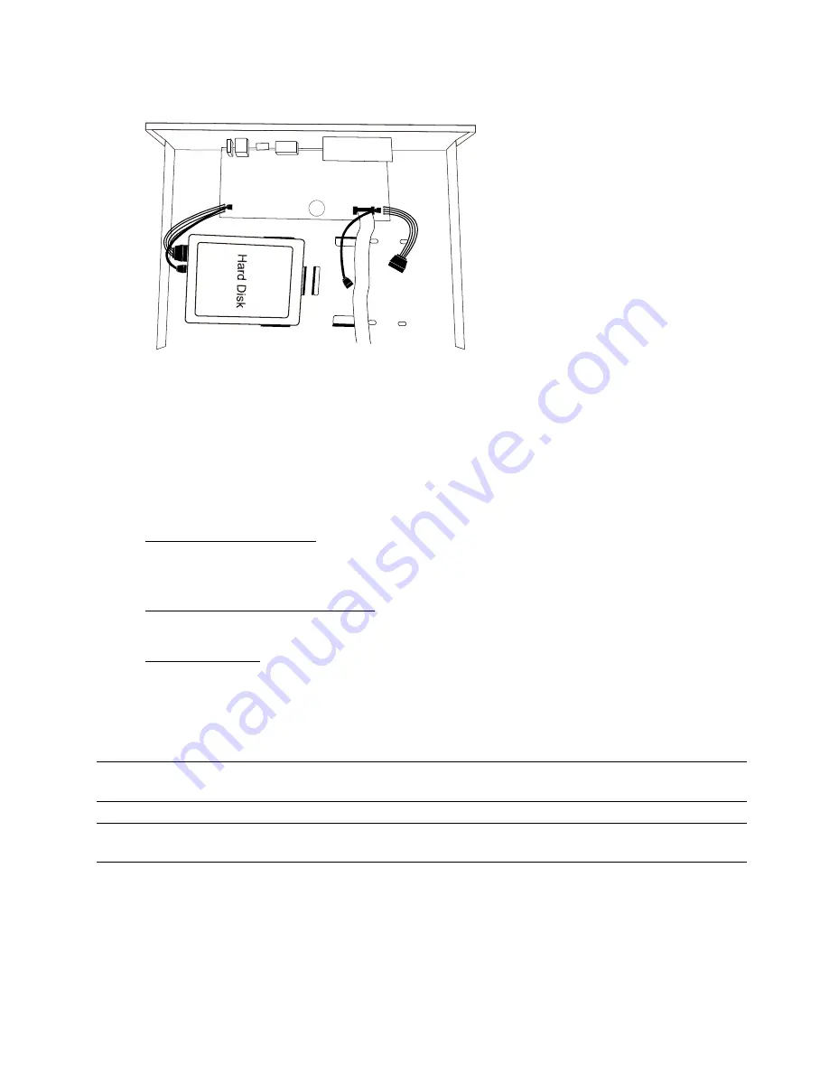
Step3: Align the screw holes on the DVR base and the hard disk. Then, fasten the hard disk o the DVR base with the
supplied screws from the bottom side of the DVR.
Step4: Connect the data bus and power cable for the hard disk.
CR2032
Step5: Replace the top cover and fasten the screws you loosened in Step1.
2.2 Camera Connection
Install the camera on the wall or ceiling based on your installation environment and camera type. For installation
details, please refer to the user manual of your camera.
2.2.1 Normal / Motorized Lens Camera
1) Connecting to DVR video input
Connect the camera video output to the DVR video input port with a coaxial cable or RCA cable with a BNC
connector.
2) Connecting to DVR audio input (Optional)
Connect the camera audio output to the DVR audio input port with an RCA cable.
3) Connecting to power
Connect the camera with indicated power supply and make sure it’s power-supplied.
2.2.2 Speed Dome Camera
The following description is taking our brand’s speed dome camera as an example.
Note:
The RS485 wiring is not needed when your DVR and speed dome camera are both our HD CCTV
series. If yes, please go to
STEP 5
directly for PTZ camera setting.
Note:
Speed dome camera connection for non-HD CCTV series is available only for selected DVR
models.
STEP 1: Get a RJ11 cable with the proper length to your connection.
Different RJ11 connector may have different wire layout, so the connection might be different. If you
cannot control the DVR after connection, please reverse the RJ11 cable connection with the DVR.
STEP 2: Remove one end of the insulating coating of the RJ11 cable.
Remove one end of the insulating coating of the RJ11 cable to find the RS485-A and the RS485-B wires,
and remove the insulating coating to reveal the naked wires for further connection.


