


o
Green — terminal 6
o
Brown/ White — terminal 7
o
Brown — terminal 8
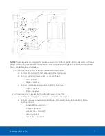
3. Connect a network cable from a network switch to the PSU:
a. Pull the cable through the third cable gland (#3 in the diagram) and terminate it with an RJ-45 jack.
b. Connect this cable to J2 (Camera 1).
4. If you are using an overview camera, connect another network cable from the network switch to the PSU:
a. Pull the cable through the fourth cable gland (#4 in the diagram) and terminate it with an RJ-45 jack.
b. Connect this cable to J3 (Camera 2).
5. Connect a 24V AC/DC power supply cable to the PSU:
NOTE:
It is recommended that you use a 24 V (secondary) 100 VA transformer.
a. Pull the cable through the fifth cable gland (#5 in the diagram).
b. Connect the red and black wires to J6 (Low Voltage AC/DC Input) terminal.
o
Red — positive
o
Black — negative
Tip:
If power is supplied to the PSU, there will be a red glow from both IR panels. You can verify this by taking a
photo of the IR panels with a phone camera. The red glow will be more visible in the photo.
CAUTION —
Do not adjust any of the potentiometers in the PSU.
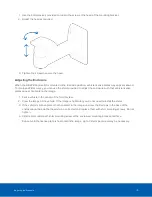
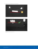
Positioning the HD LPR Capture Kit
Adjusting the Mounting Bracket
The Avigilon HD LPR Capture Kit is pre-calibrated for a specific target distance as indicated by the model
number. It is important to aim the camera at the appropriate distance.
Positioning the HD LPR Capture Kit
18