


NOTE:
The cable glands are designed for cables between 0.15 – 0.30 inches (4 – 8 mm) in diameter. For thinner
cables, thicken the cable with electrical tape at the point of contact with the gland to ensure a tight fit. Unused
glands should be plugged or sealed.
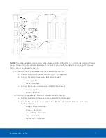
1. Connect the black power cable from the LPR camera to the PSU:
a. Pull the cable through the first cable gland (#1 in the diagram)
b. Connect the red and black wires to J4 (Lamp Power):
o
Red — positive
o
Black — negative
c. Connect the purple and white wires to J8 (15 V Aux Power):
o
Purple — positive
o
White — negative
2. Connect the gray network cable from the LPR camera to the PSU:
a. Pull the cable through the second cable gland (#2 in the diagram)
b. Connect the wires to the appropriate terminals in the punch down block labeled J1 (Camera
Combined Feed):
o
Orange/ White — terminal 1
o
Orange — terminal 2
o
Green/ White — terminal 3
o
Blue — terminal 4
o
Blue/ White — terminal 5
Connecting Cables in the PSU
17