Chapter 5: Disassembling and Expanding Leg Frames
26
Expanding a Frame with Leg Frame Join Modules
The Leg Frame Join Module consists of special center Legs and a mounting bracket that let you join two or more S6 Leg Frames
together to form a larger system. The center Legs provide frame support with a shorter bottom foot than standard Leg Frame Legs.
The bracket attaches to the Beams to join the two frames together.
If your system includes a Leg Frame Join Module, follow the instructions included with it to assemble and join both Leg Frames.
How to Proceed
After disassembling or expanding your Leg Frame, do the following.
To move an existing system:
1
Move each chassis section (and Leg Frame if applicable) following all the previously listed precautions.
2
After the components are in their new location, re-assemble Legs (if any) and chassis, then reinstall Cable Sets, modules, and
other hardware components. Refer to the
S6 Installation Guide
for step-by-step instructions.
To expand a system:
1
Follow instruction in the
S6 Installation Guide
to determine the Module layout and the new width of your frame. This determines
switch and PSU placement, and cabling requirements.
2
Re-assemble Legs (if any), re-attach and/or add new chassis, then reinstall Rear Covers, reinstall (or replace) Bolster(s), Side
Covers and other frame components.
3
If necessary, install new, or move existing Ethernet switch(es) and/or PSUs.
4
Install Cable Sets, modules, and other hardware components.
About the S6 Installation Guide
A printed copy of the
S6 Installation Guide
is included with each Master Module. For the most current installation information,
download the most recent electronic version of the
S6 Installation Guide
from your Avid master account. You can also download
a copy from the S6 Support page in the Avid Knowledge Base.
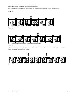
Figure 23. Two Leg Frames attached with a Leg Frame Join Module
Summary of Contents for Pro Tools S6 Master Post Module
Page 1: ...Expanding an S6 System ...
Page 4: ...Part I Introduction ...
Page 9: ...Part II Disassembly ...
Page 30: ...Part III Appendix ...
Page 33: ......

