36
5. Attach the other end of the component cable to Component input of your video deck as
follows:
a.
Connect the BNC attached to the green wire to the component input connector
labeled Y.
b.
Connect the BNC attached to the red wire to the component input connector labeled
R-Y.
c.
Connect the BNC attached to the blue wire to the component input connector
labeled B-Y.
n
Make sure you terminate the input signal if your video deck supports passthrough. See the
documentation that is provided with your video deck.
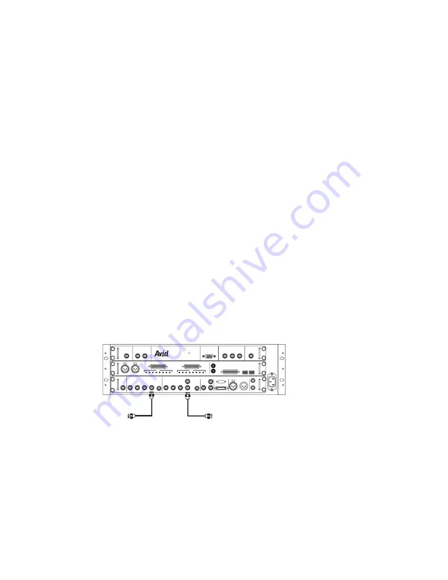
Connecting a Video Deck — Composite Signal
A composite video deck connection requires the following:
•
Two composite video cables with BNC connectors at both ends
•
A video deck with composite inputs and outputs
To connect a deck using composite signals:
1. Locate one composite video cable.
2. Attach one end of the cable to the Avid Nitris Composite output connector on the SD
video I/O board.
Connecting a Video Deck — Composite Signal
3. Attach the other end of the composite cable to Composite input of your video deck.
4. Locate another composite video cable and attach it to the Avid Nitris Composite input
on the SD video I/O board.
5. Attach the other end of the composite cable to Composite output of your video deck.
1
2
3
4
5
6
7
8
HD SDI IN
HD SDI OUT
ANALOG AUDIO IN
ANALOG IN
ANALOG OUT
SDI
DAE
LTC
SYSTEM
ANALOG AUDIO OUT
HD MONITOR OUT
MONIT
OR OUT
DIGITAL AUDIO
Y
PB
S/P DIF
PR
Y
SD SYNC
PB
PR
Y
PB
PR
HD TRILEVEL
SYNC
OUT 1
MIC 1
MIC 2
OUT 2
GAIN
1
2
3
4
5
6
7
8
GAIN
IN
IN
IN
OUT
CV 1
CV 2
OUT
OUT 1
OUT 2
OUT
2
1
IN
IN/OUT
CV S-VIDEO
S-VIDEO
NITRIS HD
HD COMPONENT OUT
OPTICAL
AES/EBU
Composite in
Composite out
To composite in
on video deck
To composite out on
video deck
Summary of Contents for Nitris
Page 58: ...58...


