background image


44


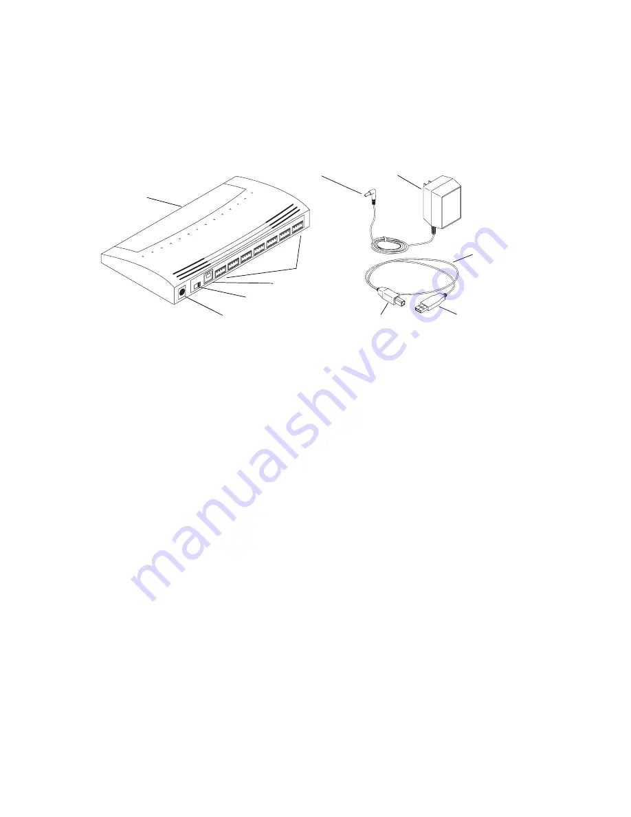
USB Hub

To connect the USB hub:

1. Connect the power adapter to the USB hub:

a.

Plug the dc connector of the ac power adapter into the USB hub power connection.

b.

Plug the ac power adapter into a wall outlet or power strip.

2. Connect the USB hub to the system using the USB cable:

a.

Plug the device connector of the USB cable into the device connection at the rear of 
the USB hub.

b.

Plug the USB connector of the USB cable into one of the USB ports at the rear of 
the system.

3. Turn on the power.

Connecting the USB Devices to the USB Hub

Once the USB hub is connected to the system, you can connect the following USB devices 
to the USB hub:

USB-to-serial adapter

USB-to-MIDI  converter

Power connection

USB hub

DC connector

AC power adapter

USB cable

USB connector

USB ports

Device connection

On/Off switch

Device connector

Summary of Contents for Nitris

Page 1: ...for your Avid Nitris can change at any time n Make sure to look at the ReadMe file that installs with the application It contains important information that is used in conjunction with the informatio...

Page 2: ...tra320 27 Formatting and Striping Media Drives 29 Avid Unity Environment 30 Reference Signal 31 Sync Topology 31 Tri level Sync 32 Black Burst Sync 32 Connecting Audio and Video Equipment 32 Connectin...

Page 3: ...k It is especially important to check each step of your workflow 2 Check the ReadMe file for the latest information that might have become available after the documentation was published Also check on...

Page 4: ...d for video and audio output Symbol or Convention Meaning or Action n A note provides important related information reminders recommendations and strong suggestions c A caution means that a specific a...

Page 5: ...nmental electrical and space requirements for your Avid Nitris workstation as well as any additional equipment Before setting up your system see the ReadMe provided with the Avid editing application t...

Page 6: ...rface that is at least 60 inches wide by 48 inches deep 150 cm 120 cm for the editing workstation Electrical Requirements Your site should meet the following electrical requirements Adequate power for...

Page 7: ...ble from HP Installation instructions are included with the kit The HP Workstation system requires 5 rack units See the following sections for more information Equipment Environmental and Safety Guide...

Page 8: ...e Earthing Maintain reliable earthing of rack mount equipment Give particular attention to supply connections other than direct connections to the branch circuit for example the use of power strips In...

Page 9: ...the baseline of a U alignment position If your rack enclosure has threaded holes continue with Securing the Avid Nitris in a Rack on page 10 Positioning the Avid Nitris 5 8 in 5 8 in 1 2 in 5 8 in 5 8...

Page 10: ...vid Nitris is secured in the front mounting rails of the rack with four rackmount screws If your rack has threaded holes use the proper rack screws for your rack If your rack does not have threaded ho...

Page 11: ...Installing an Avid Nitris 2 Align the holes in the Avid Nitris with the holes in the front mounting rail From the front of the rack enclosure insert the screws through the Avid Nitris and front mounti...

Page 12: ...cribes the Avid Nitris LEDs and power button Avid Nitris Front Panel Avid Nitris LEDs LED Status When Lit VIDEO HD The LED is illuminated in High Definition HD mode as opposed to SD Lit when the appli...

Page 13: ...Nitris is locked to the incoming Reference signal Lock Lit when a valid reference input signal is present and locked for capture Blinks if the sync signal is not valid AUDIO Pull Down Lit when audio P...

Page 14: ...d Nitris Rear Panel n If you select a downconvert format you can output HD playback and SD downconvert simultaneous through the Avid Nitris As a result you can monitor SD output or create an SD master...

Page 15: ...inition component analog RGB video signal on a 15 pin connector compatible with multisync computer monitors n The HD MONITOR OUT connector on the HD Video I O Board provides an output signal to VGA mo...

Page 16: ...l Function Eight Channel Audio I O Board Identifiers Number Label Function 1 MIC 1 Microphone MIC inputs two female XLR connectors The analog microphone connectors accept powered or 48 V phantom power...

Page 17: ...PDIF digital output red phono RCA jack 7 AES EBU IN OUT Channels 1 8 AES EBU digital input and output 25 pin DSUB connector a color coded DB25 to XLR cable is provided 8 OPTICAL IN 8 optical channels...

Page 18: ...t for a black burst or reference signal BNC connector 2 ANALOG IN Y component SD analog component video input Y luma BNC connector connects to the Y video output of decks 3 ANALOG IN PB component SD a...

Page 19: ...nput BNC connector 14 SDI OUT1 Serial Digital Interface output number 1 BNC connector 15 SDI OUT2 Serial Digital Interface output number 2 BNC connector 16 DAE Digital Audio Extraction DAE interface 9...

Page 20: ...he xw8200 workstation As more systems and third party boards are tested and qualified and as different configurations are approved they are posted on the Avid web site For the latest information conce...

Page 21: ...monitor s PCI slot 3 32 bit 33 MHz 5 V Not used Do not use This bus segment is used by the integrated 1394 and the integrated Ethernet PCI Express slot 4 x8 mechanically x4 electrically Not used Do n...

Page 22: ...dio equipment to the Avid Nitris see Connecting Audio and Video Equipment on page 32 Avid Nitris Base Board Connection c There is a similar connector on the Nitris Codec board which is currently not u...

Page 23: ...e digital interlink connector on the Avid Nitris Base board 5 Make sure both ends of the cable are secure n Turn on the Avid Nitris after you have turned on your computer 1 2 3 4 5 6 7 8 HD SDI IN HD...

Page 24: ...Mouse To connect the keyboard and mouse 1 In the base unit connect the keyboard to the top left or bottom mini DIN port 2 Connect the mouse to the top right or top mini DIN port in the base unit n On...

Page 25: ...connectors on the monitor if available For more information regarding the graphic boards and monitors see the documentation provided by the manufacturer The driver for the graphic board should be ins...

Page 26: ...itris editing systems support the Avid MediaDock Ultra320 as a local SCSI storage system Local storage connects to the two SCSI channels at the rear of the workstation and must be striped to provide t...

Page 27: ...on is half the drives attached to SCSI channel A and the other half connected to SCSI channel B For example six drives are connected to SCSI bus channel A and the remaining six drives are connected to...

Page 28: ...in single bus mode create a two way stripe across both SCSI bus channels using 24 SCSI drives 12 in each enclosure Storage Configuration with MediaDock Ultra320 Chassis in Single Bus Mode l l 0 l l 0...

Page 29: ...Avid editing system to another by using the Disk Management tool For information on moving striped drives see your Windows documentation or Disk Management Help Formatting and Striping Media Drives Di...

Page 30: ...nity Environment Avid Unity media networks are shared storage and networking solutions for sharing media between multiple workstations Depending on which Avid Unity environment you have a specific med...

Page 31: ...synced read the documentation that ships with each of your video devices c Avid Symphony Nitris requires that the VTR and the Avid Nitris hardware be genlocked to the same timing source when capturing...

Page 32: ...erence synchronizing information from the facility s master generator You must use a synchronization signal to synchronize your VTR and the Nitris video subsystem for all the HD formats supported by A...

Page 33: ...nd illustration summarizes the video connections For more information see the documentation that comes with your peripheral devices To connect video devices 1 Connect the HD In on the Avid Nitris to t...

Page 34: ...les used in the following example have three BNC connectors on each end of the cable and are color coded red green and blue 1 2 3 4 5 6 7 8 HD SDI IN HD SDI OUT ANALOG AUDIO IN ANALOG IN ANALOG OUT SD...

Page 35: ...nect the BNC attached to the blue wire to the component output connector labeled B Y 4 Locate another component video cable and attach it to the Avid Nitris outputs as follows a Connect the BNC attach...

Page 36: ...osite signals 1 Locate one composite video cable 2 Attach one end of the cable to the Avid Nitris Composite output connector on the SD video I O board Connecting a Video Deck Composite Signal 3 Attach...

Page 37: ...4 5 6 7 8 HD SDI IN HD SDI OUT ANALOG AUDIO IN ANALOG IN ANALOG OUT SDI DAE LTC SYSTEM ANALOG AUDIO OUT HD MONITOR OUT MONITOR OUT DIGITAL AUDIO Y PB S P DIF PR Y SD SYNC PB PR Y PB PR HD TRILEVEL SY...

Page 38: ...eck connection requires the following Two S Video cables A video deck with S Video inputs and outputs To connect a deck using S Video signals 1 Locate one S Video cable 2 Attach one end of the cable t...

Page 39: ...422 serial adapter Two serial cables with 9 pin male connectors at both ends To connect a single deck to your system 1 Locate the serial adapter kit 2 Attach one end of a 9 pin cable to the end of the...

Page 40: ...e on the Avid Support Center Each cable is similar in appearance using a DB 25 connector on one end and eight industry standard XLR audio connectors on the other end Audio Input and Output Cable The c...

Page 41: ...ANALOG OUT SDI DAE LTC SYSTEM ANALOG AUDIO OUT HD MONITOR OUT MONITOR OUT DIGITAL AUDIO Y PB S P DIF PR Y SD SYNC PB PR Y PB PR HD TRILEVEL SYNC OUT 1 MIC 1 MIC 2 OUT 2 GAIN 1 2 3 4 5 6 7 8 GAIN IN I...

Page 42: ...he Avid Nitris or the video the Avid Nitris sends to the deck See the documentation that came with your video deck for more information c The video you see in the monitor connected to the deck might n...

Page 43: ...using the MIDI features of the mixer USB and Serial Connections Windows systems typically have 2 or more USB connections and one serial connection If you need more than one serial connection Avid reco...

Page 44: ...the USB cable into the device connection at the rear of the USB hub b Plug the USB connector of the USB cable into one of the USB ports at the rear of the system 3 Turn on the power Connecting the US...

Page 45: ...er If you are using a JL Cooper controller or a Yamaha mixer you must install a USB to MIDI converter The MIDISPORT 2x2 by M AUDIO has been tested with the Avid Symphony Nitris system You need a USB c...

Page 46: ...ize your JL Cooper fader controllers Fader controller connections are shown for both the MCS 3000X and the FaderMaster Pro see JL Cooper MCS 3000X Fader Controller Cabling on page 47 and JL Cooper Fad...

Page 47: ...converter see USB to MIDI Converter Front Panel on page 48 and the other end of the cable into the MIDI OUT connector of the fader controller 7 Plug one end of the second MIDI cable into the Out A con...

Page 48: ...nnect the mixer 1 Quit any open applications 2 Shut down the Avid editing system 3 Make sure your USB to MIDI converter is connected to the USB port as explained in Connecting the USB to MIDI Converte...

Page 49: ...ond MIDI cable into the Out A connector of the USB to MIDI converter 8 Plug the other end of the cable into the MIDI IN connector of the mixer see the following figure 9 Make sure button on the front...

Page 50: ...ure the system was turned off in a proper manner the power cord is removed from the rear of the system and you follow the proper grounding techniques To install and remove the fan 1 Lay the system on...

Page 51: ...rds the rear of the system until you have a pressure fit carefully watching for the cables on the side of the system Lowering Fan Into Place 6 Connect the power plug n Avid uses one of the power plugs...

Page 52: ...ceived including interference that may cause undesired operation This equipment has been tested and found to comply with the limits for a Class A digital device pursuant to Part 15 of the FCC Rules Th...

Page 53: ...eclared EN60950 2000 Third Edition CISPR 22 1997 EN55022 1994 A1 1995 A2 1997 Class A EN55024 1998 EN61000 3 2 4 2 4 3 4 4 4 5 4 6 4 11 Manufacturer s Name Avid Technology Inc 1925 Andover Street Tewk...

Page 54: ...Avid Xpress DV Film Composer Media Composer MediaDock MediaDock 2 MediaDrive MediaRAID MEDIArray MEDIArray Drive MEDIArray II MEDIArray II Drive Meridien I O box Pro Tools AVoption V10 Symphony Produc...

Page 55: ...e tested in a typical Avid ProEncode Avid Unity MediaManager Avid Unity MediaNetwork includes File Manager Avid Unity TransferManager LANserver LANserver EX MEDIArray MEDIArray Drive MEDIArray II MEDI...

Page 56: ...nance extended hardware warranty and preferred pricing on replacement parts Offerings and options may vary by product and are not available for all products For more information regarding Avid s servi...

Page 57: ...RIGHTS This Software and its documentation are commercial computer software or commercial computer software documentation In the event that such Software or documentation is acquired by or on behalf...

Page 58: ...58...

Reviews: