background image

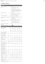
11 Dati tecnici

Dati generali

Posizione di montaggio

A piacere

Fluido

W

Aria compressa non lubrificata (gas neutri) 

W

Dimensione max. particella 5 μm 

W

Punto di rugiada in pressione min. 15 C 
inferiore alla temperatura ambiente/
del fluido, max. +3 C

Campo di pressione 

W

max. 10 bar 

W

Pressione di frenatura/tenuta 0 bar

W

Pressione di esercizio da 4 a 10 bar

Temperatura ambiente

W

da -20 °C a +70 °C (frenata),

W

da -20 °C a +80 °C (ritenuta)

Asta pistone/tondino d'acciaio

W

EN 10088-3, resistenza alla trazione 
da 800 a 1000 MPa 

W

Campo di tolleranza da e8 a h9 

W

Rugosità superficiale da R

a

 0,05 a 0,2

Indicazione del valore B

10d


secondo EN ISO 13849-1

W

B

10

 = 2 milioni (B

10d

 = 2 milioni) cicli 

di commutazione per frenata

W

B

10

 = 5 milioni (B

10d

 = 5 milioni) cicli 

di commutazione per ritenuta

Velocità massima del pistone

1 m/s

Dichiarazione di conformità

ved. 

Valori caratteristici 

Diametro pistone

32

40

50

63

80

100

125

Numero di materiale

5

230

99

64

02

5

231

99

64

02

5

232

99

64

02

5

233

99

64

02

5

234

99

64

02

5

235

99

64

02

5

236

99

64

02

Energia frenante max. 
per ciclo di frenatura

[J]

4,8

9

15

27

54

88

140

Energia frenante per 
ciclo di frenatura riferita 
a B

10d

[J]

1,6

3

5

9

18

29

47

Energia frenante totale 
max.

[10

6

 J]

3,2

6

10

18

36

58

93

Energia frenante max. 
per ora

[J]

720

1350 2250 4050 8100 13200 21000

Forza di ritenuta/
frenante max.

[N]

760

1200 1900 3000 5000 8000 12000

Peso

[kg]

1,37

1,58

2,46

3,64

6,89 10,79 16,88

Momento torcente max. 
asta pistone

[Nm]

0,5

1

2

2,5

5

9

15

Corsa cilindro max. 
per sicurezza contro 
la flessione caso 
di Eulero 1

[mm]

750

1100 1350

950

1350

 950

1500

Corsa cilindro max. 
per sicurezza contro 
la flessione caso 
di Eulero 2

[mm]

400

550

700 500 700 500 800

Massa frenata mobile 
(orizzontale)

[kg]

32

50

78

123

199

311

486

Massa frenata mobile 
(verticale 4 bar

 1)

)

1)

Pressione di esercizio del cilindro

[kg]

16

25

39

62

99

155

243

Massa frenata mobile 
(verticale 6 bar

1)

)

[kg]

24

38

58

93

149

233

364

Tempo di reazione t

break


(4 bar)

[s]

0,085 0,085 0,085 0,085 0,085 0,09

0,09

Tempo di reazione t

break


(6 bar)

[s]

0,100 0,100 0,100 0,100 0,100 0,110 0,110

Tempo di reazione t

break


(10 bar)

[s]

0,120 0,120 0,120 0,120 0,120 0,130 0,130

Portata nominale min. Q

n

Valvola di pilotaggio 
6-->5 bar

[l/min]

50

70

140

240

450

700

1200

3

AVENTICS

 | LU6 | R412013217–BAL–001–AF | Italiano

16

Summary of Contents for LU6

Page 1: ... SV Feststelleinheit LU6 LU6 Locking Unit Unité de blocage LU6 Blocca asta LU6 Unidad de retención LU6 Positionshållare LU6 LU6 Betriebsanleitung Operating instructions Notice d instruction Istruzioni per l uso Instrucciones de servicio Bruksanvisning ...

Page 2: ...g 9 9 7 3 5 4 4 5 6 6 8 2 1 2 1 1 1 2 3 4 5 6 7 8 2 Typenschild Beispiel Name plate example Exemple de plaque signalétique Esempio di targhetta di identificazione Placa de características ejemplo Exempel typskylt 3 Geräteübersicht Device overview Vue d ensemble de l appareil Panoramica dell apparecchio Vista general del aparato Översikt över enheten ...

Page 3: ...fizierten Leistungskennwerte nicht auf die Funktion auswirkt O Entnehmen Sie Normen und Kennwerte die das Produkt erfüllt einhält und voraussetzt dem Kapitel Technische Daten O Entnehmen Sie die produktrelevanten Richtlinien der Konformitätserklärung Nicht bestimmungsgemäße Verwendung Zur nicht bestimmungsgemäßen Verwendung des Produkts gehört W der Einsatz im nicht industriellen Bereich Wohnberei...

Page 4: ...stens 4 bar Dadurch werden die Klemmbacken gelöst 4 Entfernen Sie den Transportdorn 8 Bewahren Sie den Transportdorn für spätere Demontagezwecke auf 5 Schieben Sie die Feststelleinheit LU6 über die Kolbenstange des Zylinders bzw über das angefaste Ende des Rundstahls 6 Schrauben Sie die Feststelleinheit LU6 mit dem Befestigungssatz am Zylinderdeckel 3 bzw der Anlage fest Beachten Sie in beiden Fäl...

Page 5: ... Bewegung der Kolbenstange ein oder ausfahrend O Sorgen Sie vor dem Belüften der Feststelleinheit LU6 dafür dass am Kolben des Antriebszylinders ein Kräftegleichgewicht herrscht indem beispielsweise mittels einer geeigneten Steuerung beide Zylinderräume mit Druck beaufschlagt werden Beachten Sie außerdem dass es infolge der Kolbenflächendifferenz zu unerwünschten Bewegungen der Kolbenstange kommen...

Page 6: ...cherheit Eulerfall 2 mm 400 550 700 500 700 500 800 bewegliche Brems masse horizontal kg 32 50 78 123 199 311 486 bewegliche Brems masse vertikal 4 bar 1 kg 16 25 39 62 99 155 243 bewegliche Brems masse vertikal 6 bar1 kg 24 38 58 93 149 233 364 Reaktionszeit tbreak 4 bar s 0 085 0 085 0 085 0 085 0 085 0 09 0 09 Reaktionszeit tbreak 6 bar s 0 100 0 100 0 100 0 100 0 100 0 110 0 110 Reaktionszeit ...

Page 7: ...e standards and parameters complied with adhered to and required by the product O See the declaration of conformity for product relevant directives Improper use Improper use of the product includes W Use in non industrial applications residential areas W Use outside of the product limits defined in the technical data W Unauthorized modifications W Use of a lubricator in the system compressed air s...

Page 8: ...he stated tightening torques in both cases 7 Exhaust the LU6 locking unit This causes the clamping jaws to hold the piston rod in place 8 Remove the compressed air supply again from connection 9 9 Place the protective cap back inside the compressed air connection 9 before transporting the cylinder with the mounted LU6 locking unit Install the cylinder with preassembled LU6 locking unit in a system...

Page 9: ...ssential to verify the theoretical stopping distance calculated in the design by measuring the actual stopping distance before commissioning as a brake Detailed information on calculation can be found on the LU6 locking unit online catalog page Malfunction Possible cause Remedy Clamping jaws do not open The locking unit is not leaktight Disassemble it and send it to AVENTICS GmbH together with a d...

Page 10: ... Nm 0 5 1 2 2 5 5 9 15 Max cylinder stroke for buckling protection Euler case 1 mm 750 1100 1350 950 1350 950 1500 Max cylinder stroke for buckling protection Euler case 2 mm 400 550 700 500 700 500 800 Moving braking mass horizontal kg 32 50 78 123 199 311 486 Moving braking mass vertical 4 bar 1 kg 16 25 39 62 99 155 243 Moving braking mass vertical 6 bar1 kg 24 38 58 93 149 233 364 Response tim...

Page 11: ...de piston et ou du rond en acier La cartouche de blocage de l unité de blocage LU6 et la tige de piston et ou le rond en acier sont soumis à un processus d usure naturel qui ne se répercute en rien sur le fonctionnement dans les limites de valeurs caractéristiques de puissance spécifiées O Pour les normes et valeurs caractéristiques auxquelles satisfait le produit se reporter au chapitre Données t...

Page 12: ...iston et ou ronds en acier avec rugosité de surface spécifiée O Observer les valeurs caractéristiques de substances admises au chapitre Données techniques 1 2 1 Retirer le capuchon de protection du raccordement d air comprimé de l unité de blocage LU6 9 2 Raccorder l alimentation en air comprimé 3 Ventiler l unité de blocage LU6 avec minimum 4 bar Cela desserrera les mâchoires de serrage 4 Retirer...

Page 13: ...en raison des pièces de machines en mouvement O Respecter une distance de sécurité suffisante O Ne procéder à aucune intervention sur l installation en cours de fonctionnement Risque d accident dû à un mouvement incontrôlé de la tige de piston Lors de la ventilation de l unité de blocage LU6 desserrage des mâchoires si seule une chambre du vérin est alimentée en pression ou en masse cela peut caus...

Page 14: ...ge J 4 8 9 15 27 54 88 140 Energie de freinage par cycle de freinage en référence à B10d J 1 6 3 5 9 18 29 47 Energie de freinage totale max 106 J 3 2 6 10 18 36 58 93 Energie de freinage max par heure J 720 1350 2250 4050 8100 13200 21000 Force de freinage maintien max N 760 1200 1900 3000 5000 8000 12000 Poids kg 1 37 1 58 2 46 3 64 6 89 10 79 16 88 Moment de torsion max tige de piston Nm 0 5 1 ...

Page 15: ...ha nessun impatto sulla funzione nei limiti dei parametri delle prestazioni specificati O Consultare il capitolo Dati tecnici per sapere quali norme e parametri il prodotto soddisfa rispetta e prevede O Per le direttive rilevanti per il prodotto vedere la dichiarazione di conformità Utilizzo non a norma Per uso non a norma del prodotto si intende W l utilizzo in aree domestiche non industriali W l...

Page 16: ...osità superficiale specificata O Osservare le proprietà dei materiali consentite nel capitolo Dati tecnici 1 2 1 Rimuovere il tappo di protezione sul raccordo aria compressa dell unità di bloccaggio LU6 9 2 Collegare l alimentazione ad aria compressa 3 Areare l unità di bloccaggio LU6 con minimo 4 bar In questo modo si aprono le ganasce 4 Rimuovere lo spinotto di trasporto 8 Conservare lo spinotto...

Page 17: ...essione o massa ciò provoca un movimento discontinuo dell asta del pistone in entrata o in uscita O Prima dell aerazione dell unità di bloccaggio LU6 fare in modo che sul pistone del cilindro di azionamento viga un equilibrio delle forze alimentando per esempio entrambi le camere del cilindro con pressione tramite un comando adatto Osservare inoltre che in seguito alla differenza delle superfici d...

Page 18: ...ax per ciclo di frenatura J 4 8 9 15 27 54 88 140 Energia frenante per ciclo di frenatura riferita a B10d J 1 6 3 5 9 18 29 47 Energia frenante totale max 106 J 3 2 6 10 18 36 58 93 Energia frenante max per ora J 720 1350 2250 4050 8100 13200 21000 Forza di ritenuta frenante max N 760 1200 1900 3000 5000 8000 12000 Peso kg 1 37 1 58 2 46 3 64 6 89 10 79 16 88 Momento torcente max asta pistone Nm 0...

Page 19: ...nto así como en cualquier posición del vástago de émbolo o de la barra cilíndrica de acero El cartucho de retención de la unidad de retención LU6 y el vástago de émbolo la barra cilíndrica de acero están sujetos al desgaste natural este no afecta al funcionamiento siempre y cuando se respeten los valores característicos de rendimiento especificados O Puede consultar las normas y valores caracterís...

Page 20: ... la alimentación de aire comprimido 3 Aplique una presión de 4 bar como mínimo a la unidad de retención LU6 de esta forma se sueltan las mordazas de apriete 4 Retire el perno de transporte 8 Guárdelo para futuras tareas de desmontaje 5 Deslice la unidad de retención LU6 por el vástago de émbolo del cilindro o por el extremo achaflanado de la barra cilíndrica de acero 6 Atornille la unidad de reten...

Page 21: ...resión o masa a una cámara del cilindro el vástago de émbolo se mueve de forma repentina hacia dentro o hacia fuera O Antes de presurizar la unidad de retención LU6 asegúrese de que el émbolo del cilindro de accionamiento presenta un equilibrio de fuerzas p ej aplicando mediante un control adecuado presión a las dos cámaras del cilindro Así mismo tenga en cuenta que debido a la diferencia de super...

Page 22: ... de frenado J 4 8 9 15 27 54 88 140 Energía de frenado por ciclo de frenado en relación a B10d J 1 6 3 5 9 18 29 47 Energía de frenado total máx 106 J 3 2 6 10 18 36 58 93 Energía de frenado máx por hora J 720 1350 2250 4050 8100 13200 21000 Fuerza máx de retención frenado N 760 1200 1900 3000 5000 8000 12000 Peso kg 1 37 1 58 2 46 3 64 6 89 10 79 16 88 Par de torsión máx del vástago de émbolo Nm ...

Page 23: ...shållare LU6 och kolvstång resp rundstål är utsatta för naturligt slitage vilket inte inverkar på funktionen om de håller sig inom specificerade värden O I kapitlet Teknisk data finns standarder och egenskaper som produkten uppfyller innehåller och förutsätter O Se konformitetsförklaringen för de riktlinjer som är relevanta för produkten Ej avsedd användning Ej avsedd användning av produkten inneb...

Page 24: ...nderns kolvstång resp på rundstålets fasade ände 6 Skruva fast positionshållare LU6 med monteringssatsen på cylinderlocket 3 resp i anläggningen Observera i bägge fallen angivna åtdragningsmoment 7 Avlufta positionshållare LU6 Klämbackarna fixerar då kolvstången 8 Avlägsna tryckluftsmatningen från anslutningen 9 igen 9 Innan en cylinder med monterad positionshållare LU6 transporteras skall skyddkå...

Page 25: ...oretiskt beräknade stoppsträckan överensstämmer med den faktiska stoppsträckan genom att mäta den Detaljerad beräkningsinformation finns på positionshållare LU6 katalogsida i online katalogen Fel Möjlig orsak Åtgärd Klämbackar öppnas inte Positionshållaren är otät Demontera komponenten och skicka den tillsammans med en beskrivning av felet till AVENTICS GmbH Arbetstrycket är för lågt Öka arbetstry...

Page 26: ...1 2 2 5 5 9 15 max cylinderslaglängd för knäcksäkerhet Eulerfall 1 mm 750 1100 1350 950 1350 950 1500 max cylinderslaglängd för knäcksäkerhet Eulerfall 2 mm 400 550 700 500 700 500 800 rörlig bromsmassa horisontal kg 32 50 78 123 199 311 486 rörligt bromsmassa vertikal 4 bar 1 kg 16 25 39 62 99 155 243 rörligt bromsmassa vertikal 6 bar1 kg 24 38 58 93 149 233 364 Reaktionstid tbreak 4 bar s 0 085 ...

Page 27: ......

Page 28: ...m the obligation of own judgement and verification It must be remembered that our products are subject to a natural process of wear and aging An example configuration is depicted on the title page The delivered product may thus vary from that in the illustration Translation of the original operating instructions The original operating instructions were created in the German language R412013217 BAL...

Reviews: