DL205 Analog Manual, 7th Edition Rev. D
16-15
Chapter 16: F2-8AD4DA-2, 8-Ch. In / 4-Ch. Out Analog Voltage Combination
1
2
3
4
5
6
7
8
9
10
11
12
13
14
15
16
C
D
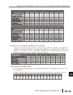
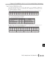
Input Track and Hold Selection Bits
The track and hold feature for each of the eight inputs can be individually configured for
minimum, maximum, no hold, or reset held value. This configuration can be changed “on the
fly” while the program is running.
V36423: (specific memory location will vary depending upon the base and slot location).
TnH = Track and hold channel n High bit
TnL = Track and hold channel n Low bit
Example: Input channel track and hold settings: 1-3 = none, ch 4-5 = minimum, ch 6-7 =
maximum, ch 8 = reset; V36423=E940(hex).
1
2
3
4
5
6
7
8
9
10
11
12
13
14
15
16
C
D
15
14 13 12 11 10
9
8
7
6
5
4
3
2
1
0
T-
8H
T-
8L
T-
7H
T-
7L
T-
6H
T-
6L
T-
5H
T-
5L
T-
4H
T-
4L
T-
3H
T-
3L
T-
2H
T-
2L
T-
1H
T-
1L
Track and Hold Select
TnH
TnL
Result
No Track and Hold
0
0
returns real time input value
Track and Hold Minimum Value
0
1
maintains lowest measured value
Track and Hold Maximum Value
1
0
maintains highest measured value
Reset Track and Hold Value
1
1
resets previously held input value
15
14 13
12
11
10
9
8
7
6
5
4
3
2
1
0
T-
8H
T-
8L
T-
7H
T-
7L
T-
6H
T-
6L
T-
5H
T-
5L
T-
4H
T-
4L
T-
3H
T-
3L
T-
2H
T-
2L
T-
1H
T-
1L
1
1
1
0
1
0
0
1
0
1
0
0
0
0
0
0
E
9
4
0
Summary of Contents for DL205
Page 1: ...DL205 Analog I O Manual Manual Number D2 ANLG M ...
Page 2: ...Notes ...
Page 6: ...Notes ...

