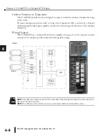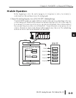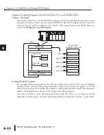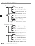
DL205 Analog Manual, 7th Edition Rev. D
5-22
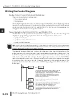
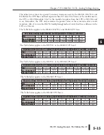
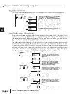
Chapter 5: F2-08AD-2, 8-Ch. Analog Voltage Input
1
2
3
4
5
6
7
8
9
10
11
12
13
14
A
B
C
D
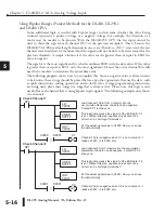
Filtering Input Noise for the DL250-1 and DL260 CPUs Only
Add the following logic to filter and smooth analog input noise in DL250-1 and DL260 CPUs.
This is especially useful when using PID loops. Noise can be generated by the field device and
or induced by field wiring.
The analog value in BCD is first converted to a binary number because there is not a BCD-
to-real conversion instruction. Memory location V1400 is the designated work space in this
example. The MULR instruction is the filter factor, which can be from 0.1–0.9. The example
uses 0.2. A smaller filter factor increases filtering. A higher precision value can be used, but it is
not generally needed. The filtered value is then converted back to binary and then to BCD. The
filtered value is stored in location V1402 for use in your application or PID loop.
NOTE:
Be careful not to do a multiple number conversion on a value. For example, if you are using the pointer method to
get the analog value, it is in BCD and must be converted to binary. However, if you are using the conventional method of
reading analog and are masking the first twelve bits, then it is already in binary and no conversion using the BIN instruction
is needed.
1
2
3
4
5
6
7
8
9
10
11
12
13
14
A
b
C
D
LD
V2000
SUBR
V1400
BTOR
SP1
BIN
Loads the analog signal, which is a BCD value
and has been loaded from V-memory location
V2000, into the accumulator. Contact SP1 is
always on.
Converts the BCD value in the accumulator to
binary. Remember, this instruction is not
needed if the analog value is originally
brought in as a binary number.
Converts the binary value in the accumulator
to a real number.
Subtracts the real number stored in location
V1400 from the real number in the accumulator,
and stores the result in the accumulator. V1400
is the designated workspace in this example.
Multiplies the real number in the
accumulator by 0.2 (the filter factor),
and stores the result in the
accumulator. This is the filtered value.
OUTD
V1400
ADDR
V1400
MULR
R0.2
OUT
V1402
BCD
RTOB
Adds the real number stored in
location V1400 to the real number
filtered value in the accumulator, and
stores the result in the accumulator.
Copies the value in the accumulator to
location V1400.
Converts the real number in the
accumulator to a binary value, and
stores the result in the accumulator.
Converts the binary value in the accumulator
to a BCD number. Note: The BCD instruction
is not needed for PID loop PV (loop PV is a
binary number).
Loads the BCD number filtered value from
the accumulator into location V1402 to use in
your application or PID loop.
Summary of Contents for DL205
Page 1: ...DL205 Analog I O Manual Manual Number D2 ANLG M ...
Page 2: ...Notes ...
Page 6: ...Notes ...

