DL205 Analog Manual, 7th Edition Rev. D
4-12
Chapter 4: F2-08AD-1, 8-Channel Analog Current Input
1
2
3
4
5
6
7
8
9
10
11
12
13
14
A
B
C
D
1
2
3
4
5
6
7
8
9
10
11
12
13
14
A
b
C
D
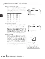
Active Channel Indicator Inputs
Three of the inputs are binary-encoded to indicate
the active channel (remember, the V-memory bits are
mapped directly to discrete inputs). The inputs are
automatically turned on and off to indicate the active
channel for each scan.
Scan X34 X35 X36 Channel
N
Off
Off
Off 1
N+1
On Off Off 2
N+2
Off On
Off 3
N+3
On On Off 4
N+4 Off Off
On
5
N+5
On Off On 6
N+6
Off On On 7
N+7
On On On 8
Module Diagnostic Inputs
The last input (X37 in this example) is the broken
transmitter and missing 24 volts input power
indicator.
When X37 is on, the input transmitter may be
broken for the corresponding input. If there is no
external 24 volts input power, or if there is a loose
or missing terminal block, then X37 goes on and a
value of zero is returned for all enabled channels.
Module Resolution
Since the module has 12-bit resolution, the analog
signal is converted into 4096 counts ranging from
0 - 4095 (2
12
). For example, a 4 mA signal would
be 0 and a 20 mA signal would be 4095. This is
equivalent to a binary value of 0000 0000 0000 to
1111 1111 1111, or 000 to FFF hexadecimal. The
diagram shows how this relates to the signal range.
Each count can also be expressed in terms of the
signal level by using the equation shown.
= channel inputs
X
3
5
V40401
B
S
L
B
S
M
X
2
0
X
3
4
X
3
6
= diagnostic inputs
X
3
7
V40401
B
S
L
B
S
M
X
2
0
20 mA
4 mA
0
4095
4 -- 20 mA
Resolution
=
H
−
L
4095
H = high limit of the signal range
L = low limit of the signal range
16 mA / 4095 = 3.907
μ
A per count
Summary of Contents for DL205
Page 1: ...DL205 Analog I O Manual Manual Number D2 ANLG M ...
Page 2: ...Notes ...
Page 6: ...Notes ...

