Section 03
ENGINE
Subsection 10
(CRANKSHAFT/BALANCER SHAFT)
VMR2004_133_03_10A.FM
03-10-7
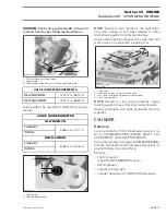
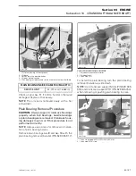
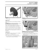
1. PTO plain bearing without groove
2. Oil bore
3. Split of the plain bearing halves
4. Cylinder base direction
A. Plain bearing inside diameter to be measured in area of oil bore
Check oil seal
no. 11
if brittle, hard or otherwise
damaged
.
Replace if necessary.
NOTE:
The oil seal is removed easily with a flat
screwdriver.
Plain Bearing Removal Procedure
CAUTION:
Always support crankcase housings
properly when ball bearings, needle bearings
or plain bearings are removed. Crankcase hous-
ing damages may occur if this procedure is not
performed correctly.
NOTE:
Always use a press for removal or installa-
tion of plain bearing halves.
Remove plain bearings
no. 9
and
no. 10
with the
plain bearing remover/installer (P/N 529 035 917).
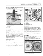
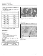
PUSH PLAIN BEARINGS OUTSIDE
1. Plain bearing remover/installer
2. Plain bearing
3. Crankcase PTO
To install the plain bearing turn the plain bearing
remover/installer up side down.
NOTE:
Use crankcase support MAG (P/N 529 035
916) and crankcase support PTO (P/N 529 035 754)
when removing or pushing plain bearing in place.
1. Crankcase support MAG (P/N 529 035 916)
2. Crankcase MAG side
PLAIN BEARING INSIDE DIAMETER (MAG/PTO)
SERVICE LIMIT
42.070 mm (1.6563 in)
2
R400motr42A
3
4
A
1
2
1
R400motr45A
3
2
R400motr43A
1

