Section 03
ENGINE
Subsection 12
(CVT)
VMR2004_135_03_12A.FM
03-12-5
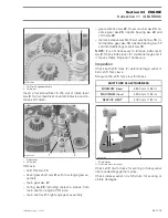
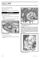
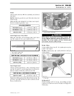
Remove drive pulley screw
no. 5
, spring washer
no. 6
and thrust washer
no. 7
.
1. Drive pulley screw
2. Spring washer
3. Thrust washer
4. Drive pulley sliding half
Push the sliding half
no. 8
of the drive pulley by hand
then remove the screw completely.
Slowly release sliding half.
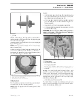
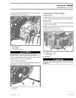
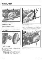
Screw clutch puller (P/N 529 035 746) in fixed half
no. 9
then withdraw fixed pulley.
1. Clutch puller
2. Fixed half
Disassembly of Drive Pulley
Governor Cup
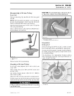
Carefully lift governor cup
no. 10
until slider shoes
no. 11
come at their highest position into guides.
Sliding Half
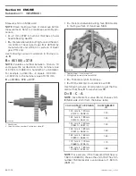
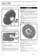
Unscrew lock nut
no. 12
and remove centrifugal
lever pivot bolt
no. 13
.
NOTE:
Outlander 400 shows 4 lever pivot bolt and
Outlander 330 only 3 levers.
Remove centrifugal lever
no. 14
.
1. Lock nut
2. Centrifugal lever pivot bolt
3. Centrifugal lever
Fixed Half
WARNING
Sliding half of drive pulley is spring loaded.
4
R400motr162A
3
2
1
1
R400motr163A
2
WARNING
Always wear safety glasses to remove spring
sleeves.
1
R400motr165A
3
2

