Section 03
ENGINE
Subsection 09
(CYLINDER AND HEAD)
VMR2004_132_03_09A.FM
03-09-25
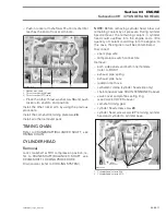
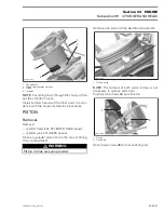
1. Piston
2. Feeler gauge
Ring End Gap
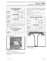
Measure position for ring end gap in the area of 8
to 16 mm (.315 to .630 in) from top of cylinder.
NOTE:
In order to correctly position the ring in the
cylinder, use piston as a pusher.
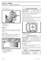
Using a feeler gauge, check ring end gap. Replace
ring if gap exceeds above described specified tol-
erance.
Installation
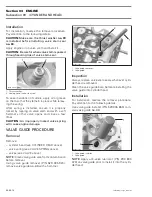
For installation, reverse the removal procedure.
Pay attention to the following details.
NOTE:
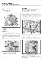
First install spring and then rings of oil
scraper ring.
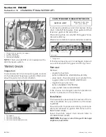
Install the oil scraper ring first, then the lower com-
pression ring with the word “N and TOP “ facing
up, then the upper compression ring with the word
“N and TOP“ facing up.
1. Upper compression ring
2. Lower compression ring
3. Oil scraper ring
CAUTION:
Ensure that top and second rings are
not interchanged.
NOTE:
Use a ring expander to prevent breakage
during installation. The oil ring must be installed by
hand.
Check that rings rotate smoothly after installation.
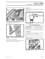
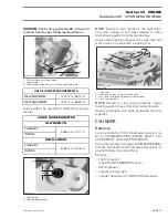
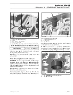
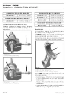
Space the piston ring end gaps 120° apart and do
not align the gaps with the piston pin bore or the
thrust side axis.
1. DO NOT align ring gap with piston thrust side axis
2. DO NOT align ring gap with piston pin bore axis
A. 120°
RING END GAP
NEW MINIMUM
UPPER
COMPRESSION RING
0.20 mm (.008 in)
LOWER
COMPRESSION RING
0.20 mm (.008 in)
OIL SCRAPER RING
0.20 mm (.008 in)
NEW MAXIMUM
UPPER
COMPRESSION RING
0.40 mm (.014 in)
LOWER
COMPRESSION RING
0.40 mm (.014 in)
OIL SCRAPER RING
0.70 mm (.028 in)
SERVICE LIMIT
ALL
1.5 mm (.059 in)
1
R400motr103A
2
A31C2NA
1
2
3
A31C2OA
1
2
A
A
A

