Section 03
ENGINE
Subsection 05
(COOLING SYSTEM)
VMR2004_128_03_05A.FM
03-05-9
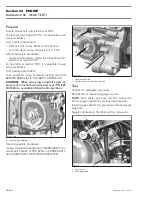
1. Special area for oil seal removal
Inspection
Inspect water pump gear for wear and damage on
the snap mechanism to the needle pin. Replace if
damaged.
Water pump shaft with rotary seal must rotate free-
ly. Otherwise, replace it.
NOTE:
When removing water pump shaft, always
replace together retaining ring, oil seal, water pump
shaft with rotary seal with new parts.
Installation
For installation, reverse the removal procedure.
However, pay attention to the following.
NOTE:
Never use oil in the press fit area of the oil
seal and rotary seal.
Push water pump shaft oil seal in place by using the
oil seal pusher (P/N 529 035 757).
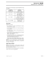
1. Oil seal for the water pump shaft
2. Oil seal pusher (P/N 529 035 757)
3. Handle for insertion jig (P/N 420 877 255)
It is recommended to install the water pump shaft
assembly using the water pump ceramic seal in-
staller (P/N 529 035 766).
NOTE:
The water pump shaft assembly has to be
pushed using the outside area of the rotary seal.
1. Surface to push water pump shaft assembly in place
CAUTION:
Never use a hammer for the rotary
seal installation. Only use a press to avoid dam-
aging the ceramic component.
1
R400motr146A
1
R400motr147A
3
2
1
R400motr150A


