Section 03
ENGINE
Subsection 09
(CYLINDER AND HEAD)
VMR2004_132_03_09A.FM
03-09-11
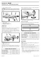
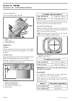
– Push in rocker arm shaft
no. 11
until its chamfer
reaches the end of rocker arm bore.
1. Rocker arm shaft
2. Thrust washer (MAG side)
3. Thrust washer (PTO side)
– Place the other thrust washer
no. 16
and push
rocker arm shaft to end position.
Install the other rocker arm by using the previous
procedure.
Install the camshaft retaining plate
no. 26
.
Install all other removed parts.
TIMING CHAIN
Refer to CRANKSHAFT/BALANCER SHAFT, see
TIMING CHAIN.
CYLINDER HEAD
Removal
Lock crankshaft at TDC compression position, re-
fer to CRANKSHAFT/BALANCER SHAFT, see
CRANKSHAFT LOCKING PROCEDURE.
Drain coolant (refer to COOLING SYSTEM).
NOTE:
Before removing cylinder head, blow out
remaining coolant by air pressure. During cylinder
head removal, the remaining coolant in cylinder
head could overflow into the engine and a little
quantity of coolant could drop into the engine. In
this case, the engine oil will be contaminated.
Disconnect:
– spark plug wire
– temperature switch connectors.
Remove:
– both side panels and both inner fenders
(refer to BODY)
– exhaust pipe spring
– exhaust pipe nuts
– radiator inlet hose
– carburetor clamp (cylinder head side only)
– chain tensioner (see CHAIN TENSIONER
above)
– valve cover and profile sealing ring
(see VALVE COVER
above)
– camshaft timing gear
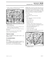
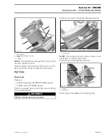
– cylinder head screws
no. 28
– cylinder head screws
no. 27
retaining cylinder
head and cylinder to cylinder base.
1. Cylinder head screws M6
2. Cylinder head screws M10
R400motr66B
1
2
3
R400motr71A
2
1


